Videos
(a)
The temperature rise in open die forging of cylinder for no friction between the flat dies and the specimen.
(a)
Explanation of Solution
Given:
The initial thickness of the specimen is
The initial radius of the specimen is
The friction coefficient is
Formula used:
The expression for the flow stress is given as,
Here,
The expression for the true strain is given as,
Here,
The expression for the final radius by equating the volume is given as,
The expression for the forging force is given as,
Here,
The expression for the average pressure is given as,
The expression for final height for
The expression for final height for
The expression forfinal height for
The expression for final height for
The expression for final height for
The expression for the temperature rise is given as,
Here
Calculation:
For
The final height can be calculated as,
The final radius can be calculated as,
The true strain can be calculated as,
The flow stress can be calculated as,
Refer to table 2.2 “Typical values of strength coefficient
The average pressure can be calculated as,
The forging force can be calculated as,
For
The final height can be calculated as,
The final radius can be calculated as,
The true strain can be calculated as,
The flow stress can be calculated as,
Refer to table 2.2 “Typical values of strength coefficient
The average pressure can be calculated as,
The forging force can be calculated as,
For
The final height can be calculated as,
The final radius can be calculated as,
The true strain can be calculated as,
The flow stress can be calculated as,
Refer to table 2.2 “Typical values of strength coefficient
The average pressure can be calculated as,
The forging force can be calculated as,
For
The final height can be calculated as,
The final radius can be calculated as,
The true strain can be calculated as,
The flow stress can be calculated as,
Refer to table 2.2 “Typical values of strength coefficient
The average pressure can be calculated as,
The forging force can be calculated as,
For
The final height can be calculated as,
The final radius can be calculated as,
The true strain can be calculated as,
The flow stress can be calculated as,
Refer to table 2.2 “Typical values of strength coefficient
The average pressure can be calculated as,
The forging force can be calculated as,
For
| Reduction (in ) | Forging force (in ) | Area under curve (in ) |
| 2.1635 |
Work done can be calculated by the summation of the area under the curve.
Refer to table of properties of common engineering materials “Typical values of density and heat capacity” for annealed copper is,
Change in temperature can be calculated as,
The figure (1) shows the curve between the forging force and reduction in height.
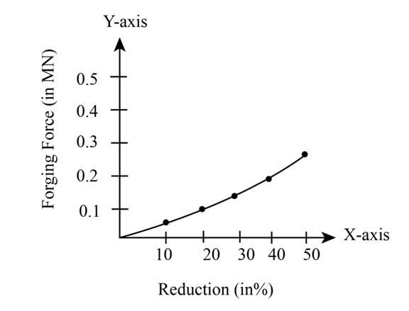
Figure (1)
(b)
The temperature risein open die forging of cylinder for
(b)
Explanation of Solution
Given:
The initial thickness of the specimen is
The initial radius of the specimen is
The friction coefficient is
Formula used:
The expression for the flow stress is given as,
Here,
The expression for the true strain is given as,
Here,
The expression for the final radius by equating the volume is given as,
The expression for the forging force is given as,
Here,
The expression for the average pressure is given as,
The expression for final height for
The expression for final height for
The expression forfinal height for
The expression for final height for
The expression for final height for
The expression for the temperature rise is given as,
Here
Calculation:
For
The final height can be calculated as,
The final radius can be calculated as,
The true strain can be calculated as,
The flow stress can be calculated as,
Refer to table 2.2 “Typical values of strength coefficient
The average pressure can be calculated as,
The forging force can be calculated as,
For
The final height can be calculated as,
The final radius can be calculated as,
The true strain can be calculated as,
The flow stress can be calculated as,
Refer to table 2.2 “Typical values of strength coefficient
The average pressure can be calculated as,
The forging force can be calculated as,
For
The final height can be calculated as,
The final radius can be calculated as,
The true strain can be calculated as,
The flow stress can be calculated as,
Refer to table 2.2 “Typical values of strength coefficient
The average pressure can be calculated as,
The forging force can be calculated as,
For
The final height can be calculated as,
The final radius can be calculated as,
The true strain can be calculated as,
The flow stress can be calculated as,
Refer to table 2.2 “Typical values of strength coefficient
The average pressure can be calculated as,
The forging force can be calculated as,
For
The final height can be calculated as,
The final radius can be calculated as,
The true strain can be calculated as,
The flow stress can be calculated as,
Refer to table 2.2 “Typical values of strength coefficient
The average pressure can be calculated as,
The forging force can be calculated as,
For
| Reduction (in ) | Forging force (in ) | Area under curve (in ) |
Work done can be calculated by the summation of the area under the curve.
Refer to table of properties of common engineering materials “Typical values of density and heat capacity” for annealed copper is,
Change in temperature can be calculated as,
The figure (2) shows the curve between the forging force and reduction in height.
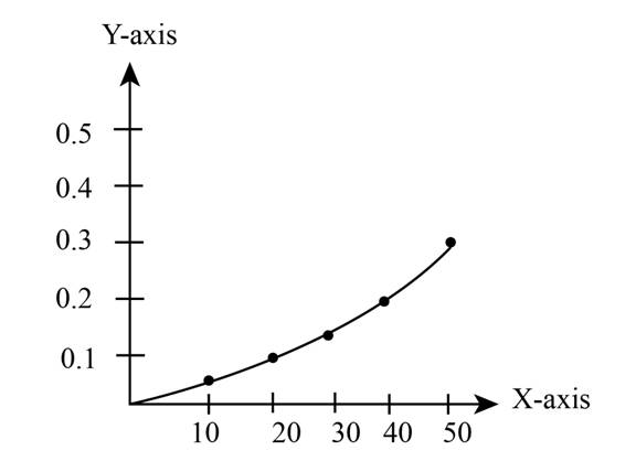
Figure (2)
Want to see more full solutions like this?
Chapter 6 Solutions
Manufacturing Processes for Engineering Materials (6th Edition)


- Q1/ For what value of x do the power series converge: 8 (-1)n-1. x2n-1 2n-1 x3 x5 = X n=1 3 Q2/ Find the Interval of convergence and Radius of convergence of the series: 8 n Σ 3+1 n=1 (x)"arrow_forwardExample-1: l D A uniform rotor of length 0.6 m and diameter 0.4 m is made of steel (density 7810 kg/m³) is supported by identical short bearings of stiffness 1 MN/m in the horizontal and vertical directions. If the distance between the bearings is 0.7 m, determine the natural frequencies and plot whirl speed map. Solution: Barrow_forwardfind the laplace transform for the flowing function 2(1-e) Ans. F(s)=- S 12) k 0 Ans. F(s)= k s(1+e) 0 a 2a 3a 4a 13) 2+ Ans. F(s)= 1 s(1+e") 3 14) f(t)=1, 0arrow_forwardFind the solution of the following Differential Equations Using Laplace Transforms 1) 4y+2y=0. y(0)=2. y'(0)=0. 2) y+w²y=0, (0)=A, y'(0)=B. 3) +2y-8y 0. y(0)=1. y'(0)-8. 4)-2-3y=0, y(0)=1. y'(0)=7. 5) y-ky'=0, y(0)=2, y'(0)=k. 6) y+ky'-2k²y=0, y(0)=2, y'(0) = 2k. 7) '+4y=0, y(0)=2.8 8) y+y=17 sin(21), y(0)=-1. 9) y-y-6y=0, y(0)=6, y'(0)=13. 10) y=0. y(0)=4, y' (0)=0. 11) -4y+4y-0, y(0)=2.1. y'(0)=3.9 12) y+2y'+2y=0, y(0)=1, y'(0)=-3. 13) +7y+12y=21e". y(0)=3.5. y'(0)=-10. 14) "+9y=10e". y(0)=0, y'(0)=0. 15) +3y+2.25y=91' +64. y(0)=1. y'(0) = 31.5 16) -6y+5y-29 cos(2t). y(0)=3.2, y'(0)=6.2 17) y+2y+2y=0, y(0)=0. y'(0)=1. 18) y+2y+17y=0, y(0)=0. y'(0)=12. 19) y"-4y+5y=0, y(0)=1, y'(0)=2. 20) 9y-6y+y=0, (0)-3, y'(0)=1. 21) -2y+10y=0, y(0)=3, y'(0)=3. 22) 4y-4y+37y=0, y(0)=3. y'(0)=1.5 23) 4y-8y+5y=0, y(0)=0, y'(0)=1. 24) ++1.25y-0, y(0)=1, y'(0)=-0.5 25) y 2 cos(r). y(0)=2. y'(0) = 0. 26) -4y+3y-0, y(0)=3, y(0) 7. 27) y+2y+y=e y(0)=0. y'(0)=0. 28) y+2y-3y=10sinh(27), y(0)=0. y'(0)=4. 29)…arrow_forwardAuto Controls A union feedback control system has the following open loop transfer function where k>0 is a variable proportional gain i. for K = 1 , derive the exact magnitude and phase expressions of G(jw). ii) for K = 1 , identify the gaincross-over frequency (Wgc) [where IG(jo))| 1] and phase cross-overfrequency [where <G(jw) = - 180]. You can use MATLAB command "margin" to obtain there quantities. iii) Calculate gain margin (in dB) and phase margin (in degrees) ·State whether the closed-loop is stable for K = 1 and briefly justify your answer based on the margin . (Gain marginPhase margin) iv. what happens to the gain margin and Phase margin when you increase the value of K?you You can use for loop in MATLAB to check that.Helpful matlab commands : if, bode, margin, rlocus NO COPIED SOLUTIONSarrow_forwardThe 120 kg wheel has a radius of gyration of 0.7 m. A force P with a magnitude of 50 N is applied at the edge of the wheel as seen in the diagram. The coefficient of static friction is 0.3, and the coefficient of kinetic friction is 0.25. Find the acceleration and angular acceleration of the wheel.arrow_forwardAuto Controls Using MATLAB , find the magnitude and phase plot of the compensators NO COPIED SOLUTIONSarrow_forward4-81 The corner shown in Figure P4-81 is initially uniform at 300°C and then suddenly exposed to a convection environment at 50°C with h 60 W/m². °C. Assume the = 2 solid has the properties of fireclay brick. Examine nodes 1, 2, 3, 4, and 5 and deter- mine the maximum time increment which may be used for a transient numerical calculation. Figure P4-81 1 2 3 4 1 cm 5 6 1 cm 2 cm h, T + 2 cmarrow_forwardAuto Controls A union feedback control system has the following open loop transfer function where k>0 is a variable proportional gain i. for K = 1 , derive the exact magnitude and phase expressions of G(jw). ii) for K = 1 , identify the gaincross-over frequency (Wgc) [where IG(jo))| 1] and phase cross-overfrequency [where <G(jw) = - 180]. You can use MATLAB command "margin" to obtain there quantities. iii) Calculate gain margin (in dB) and phase margin (in degrees) ·State whether the closed-loop is stable for K = 1 and briefly justify your answer based on the margin . (Gain marginPhase margin) iv. what happens to the gain margin and Phase margin when you increase the value of K?you You can use for loop in MATLAB to check that.Helpful matlab commands : if, bode, margin, rlocus NO COPIED SOLUTIONSarrow_forwardAuto Controls Hand sketch the root Focus of the following transfer function How many asymptotes are there ?what are the angles of the asymptotes?Does the system remain stable for all values of K NO COPIED SOLUTIONSarrow_forward-400" 150" in Datum 80" 90" -280"arrow_forwardUsing hand drawing both of themarrow_forwardarrow_back_iosSEE MORE QUESTIONSarrow_forward_ios
 Principles of Heat Transfer (Activate Learning wi...Mechanical EngineeringISBN:9781305387102Author:Kreith, Frank; Manglik, Raj M.Publisher:Cengage Learning