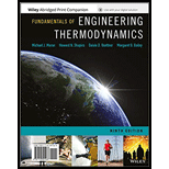
FUND OF ENG THERMODYN(LLF)+WILEYPLUS
9th Edition
ISBN: 9781119391777
Author: MORAN
Publisher: WILEY
expand_more
expand_more
format_list_bulleted
Question
error_outline
This textbook solution is under construction.
Students have asked these similar questions
Homework#5
Member AB has the angular velocity wAB = 2.5 rad/s and
angular acceleration a AB = 9 rad/s². (Figure 1)
Determine the magnitude of the velocity of point C at the instant shown.
Determine the direction of the velocity of point C at the instant shown.
Determine the magnitude of the acceleration of point C at the instant shown.
Determine the direction of the acceleration of point C at the instant shown.
A
300 mm
WAB
α AB
B
500 mm
0=60°
y
200 mm
You are asked to design a unit to condense ammonia. The required condensation rate is 0.09kg/s. Saturated ammonia at 30 o C is passed over a vertical plate (10 cm high and 25 cm wide).The properties of ammonia at the saturation temperature of 30°C are hfg = 1144 ́10^3 J/kg andrv = 9.055 kg/m 3 . Use the properties of liquid ammonia at the film temperature of 20°C (Ts =10 o C):Pr = 1.463
rho_l= 610.2 kf/m^3
liquid viscosity= 1.519*10^-4 kg/ ms
kinematic viscosity= 2.489*10^-7 m^2/s
Cpl= 4745 J/kg C
kl=0.4927 W/m Ca)Calculate the surface temperature required to achieve the desired condensation rate of 0.09 kg/s( should be 688 degrees C) b) Show that if you use a bigger vertical plate (2.5 m-wide and 0.8 m-height), the requiredsurface temperature would be now 20 o C. You may use all the properties given as an initialguess. No need to iterate to correct for Tf. c) What if you still want to use small plates because of the space constrains? One way to getaround this problem is to use small…
Knowledge Booster
Similar questions
- If you have a spring mass damper system, given by m*x_double_dot + c*x_dot + kx = 0 where m, c, k (all positive scalars) are the mass, damper coefficient, and spring coefficient, respectively. x ∈ R represents the displacement of the mass. Let us then discuss the stability of the system by using Lyapunov stability theorem. Consider the system energy as a candidate Lyapunov function shown in the image. Discuss the positive definiteness of V (x, x_dot). Derive the Lyapunov rate of this system (i.e., V_dot ), and discuss the stability property of thesystem based on the information we gain from ̇V_dot .arrow_forwardIn class, two approaches—Theorems 1 and 2 below—are discussed to prove asymptotic stability of asystem when ̇V = 0. Show the asymptotic stability of the system given in Eq. (1) by applying Theorem 1. Show the asymptotic stability of the system given in Eq. (1) by applying Theorem 2.arrow_forwardHomework#5arrow_forwardIf you have a spring mass damper system, given by m*x_double_dot + c*x_dot + kx = 0 where m, c, k (all positive scalars) are the mass, damper coefficient, and spring coefficient, respectively. x ∈ R represents the displacement of the mass. Using linear stability analysis, show that the system is asymptotically stable. Hint: stability of a linear system z_dot = Az is characterized by the eigenvalues of A.arrow_forwardWhat would the electropneumatic diagram of a circuit with the sequence a+b+c+(a-b-c-) look like?arrow_forward### What would the electropneumatic diagram of a circuit with the sequence a+b+c+(a-b-c-) look like, with a counter, in the fluidsim?arrow_forwardYou are asked to design a unit to condense ammonia. The required condensation rate is 0.09kg/s. Saturated ammonia at 30 o C is passed over a vertical plate (10 cm high and 25 cm wide).The properties of ammonia at the saturation temperature of 30°C are hfg = 1144 ́10^3 J/kg andrv = 9.055 kg/m 3 . Use the properties of liquid ammonia at the film temperature of 20°C (Ts =10 o C):Pr = 1.463 rho_l= 610.2 kf/m^3 liquid viscosity= 1.519*10^-4 kg/ ms kinematic viscosity= 2.489*10^-7 m^2/s Cpl= 4745 J/kg C kl=0.4927 W/m CCalculate the surface temperature required to achieve the desired condensation rate of 0.09 kg/s( should be 688 degrees C) a) Show that if you use a bigger vertical plate (2.5 m-wide and 0.8 m-height), the requiredsurface temperature would be now 20 o C. You may use all the properties given as an initialguess. No need to iterate to correct for Tf. b) What if you still want to use small plates because of the space constrains? One way to getaround this problem is to use small…arrow_forwardarrow_back_iosSEE MORE QUESTIONSarrow_forward_iosRecommended textbooks for you
 Elements Of ElectromagneticsMechanical EngineeringISBN:9780190698614Author:Sadiku, Matthew N. O.Publisher:Oxford University Press
 Mechanics of Materials (10th Edition)Mechanical EngineeringISBN:9780134319650Author:Russell C. HibbelerPublisher:PEARSON
 Thermodynamics: An Engineering ApproachMechanical EngineeringISBN:9781259822674Author:Yunus A. Cengel Dr., Michael A. BolesPublisher:McGraw-Hill Education
 Control Systems EngineeringMechanical EngineeringISBN:9781118170519Author:Norman S. NisePublisher:WILEY
 Mechanics of Materials (MindTap Course List)Mechanical EngineeringISBN:9781337093347Author:Barry J. Goodno, James M. GerePublisher:Cengage Learning
 Engineering Mechanics: StaticsMechanical EngineeringISBN:9781118807330Author:James L. Meriam, L. G. Kraige, J. N. BoltonPublisher:WILEY
 Elements Of ElectromagneticsMechanical EngineeringISBN:9780190698614Author:Sadiku, Matthew N. O.Publisher:Oxford University Press
 Mechanics of Materials (10th Edition)Mechanical EngineeringISBN:9780134319650Author:Russell C. HibbelerPublisher:PEARSON
 Thermodynamics: An Engineering ApproachMechanical EngineeringISBN:9781259822674Author:Yunus A. Cengel Dr., Michael A. BolesPublisher:McGraw-Hill Education
 Control Systems EngineeringMechanical EngineeringISBN:9781118170519Author:Norman S. NisePublisher:WILEY
 Mechanics of Materials (MindTap Course List)Mechanical EngineeringISBN:9781337093347Author:Barry J. Goodno, James M. GerePublisher:Cengage Learning
 Engineering Mechanics: StaticsMechanical EngineeringISBN:9781118807330Author:James L. Meriam, L. G. Kraige, J. N. BoltonPublisher:WILEY