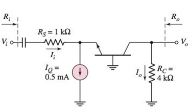
Consider the ac equivalent common−base circuit shown in Figure P6.61. The transistor has parameters β = 110 and V A = ∞ . Determine (a) the voltage gain A υ = V o / V i , (b) the current gain A i = I o / I i , (c) the input resistance R i , and (d) the output resistance R o . Figure P6.61
Consider the ac equivalent common−base circuit shown in Figure P6.61. The transistor has parameters β = 110 and V A = ∞ . Determine (a) the voltage gain A υ = V o / V i , (b) the current gain A i = I o / I i , (c) the input resistance R i , and (d) the output resistance R o . Figure P6.61
Solution Summary: The value of the small signal value voltage gain is given by the expression as shown below.
Consider the ac equivalent common−base circuit shown in Figure P6.61. The transistor has parameters
β
=
110
and
V
A
=
∞
. Determine (a) the voltage gain
A
υ
=
V
o
/
V
i
, (b) the current gain
A
i
=
I
o
/
I
i
, (c) the input resistance
R
i
, and (d) the output resistance
R
o
.
Problem 1: Two-Force Equilibrium
A 12 kg traffic light is suspended by two cables
attached to a ceiling. Determine the force in Cable 1
(AB) and Cable 2 (AC). In other words, determine the
tension in each cable, assuming the system is in static
equilibrium.
B
If the Z-axis changes, what is the effect
A circularly polarized wave, traveling in the +z-direction, is received by an elliptically
polarized antenna whose reception characteristics near the main lobe are given approx-
imately by
E₁ = (2â, + jâ] f(r. 8. d)
Find the polarization loss factor PLF (dimensionless and in dB) when the incident wave
is
(a) right-hand (CW)
(b) left-hand (CCW)
An elliptically polarized wave traveling in the negative z-direction is received by a circularly polarized
antenna. The vector describing the polarization of the incident wave is given by Ei= 2ax + jay .Find the
polarization loss factor PLF (dimensionless and in dB) when the wave that would be transmitted by the
antenna is (a) right-hand CP (b) left-hand CP.
Medium 1 is a lossless dielectric (ε₁=ε,ε, μ₁=μ₁, σ₁=0)
Medium 2 is a lossless dielectric (ε=&&₂, μ=μ₁, σ₁=0)
[бг Мо о =
= 0]
[2 Mo σ₂ = 0]
E₁ (z) = Ele² + Пe+jB₁²]
E2 (z) = E Te² and
tot
= constant
1. For the case εr1 = 1, &r2= 16, E₁x=1 V/m and a frequency f = 750 MHz determine:
λι
=
n₁ =
22 =
n2=
r =
T=
2. The magnitude |E1 tot (z)| will show an interference pattern in region 1 as:
E˜(z)=E,{1+Te®®]e¯MS =E||{1+Te^^^^\]e=##} | = |E|+Texp(j)
For an incident field E₁x=1 V/m SKETCH the magnitude of E1 tot (z)| and |E20 (z) on the graph
below. Plot the values at 2/4 increments and sketch between. What is the SWR?
Need a deep-dive on the concept behind this application? Look no further. Learn more about this topic, electrical-engineering and related others by exploring similar questions and additional content below.


 Introductory Circuit Analysis (13th Edition)Electrical EngineeringISBN:9780133923605Author:Robert L. BoylestadPublisher:PEARSON
 Delmar's Standard Textbook Of ElectricityElectrical EngineeringISBN:9781337900348Author:Stephen L. HermanPublisher:Cengage Learning
 Programmable Logic ControllersElectrical EngineeringISBN:9780073373843Author:Frank D. PetruzellaPublisher:McGraw-Hill Education
 Fundamentals of Electric CircuitsElectrical EngineeringISBN:9780078028229Author:Charles K Alexander, Matthew SadikuPublisher:McGraw-Hill Education
 Electric Circuits. (11th Edition)Electrical EngineeringISBN:9780134746968Author:James W. Nilsson, Susan RiedelPublisher:PEARSON
 Engineering ElectromagneticsElectrical EngineeringISBN:9780078028151Author:Hayt, William H. (william Hart), Jr, BUCK, John A.Publisher:Mcgraw-hill Education,