Fundamentals of Electromagnetics with Engineering Applications
5th Edition
ISBN: 9780471263555
Author: Stuart M. Wentworth
Publisher: John Wiley & Sons
expand_more
expand_more
format_list_bulleted
Concept explainers
Textbook Question
Chapter 6, Problem 6.47P
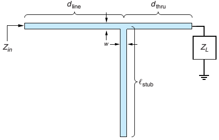
The top-down view of a microstrip circuit is shown in Figure 6.54. If the microstrip is supported by a 40-mil-thick alumina substrate, (a) determine the line width required to achieve a

Figure 6.54 The top-down view of an open-ended microstrip stub-matching circuit for Problems 6.47 and 6.48.
Expert Solution & Answer
Want to see the full answer?
Check out a sample textbook solution
Students have asked these similar questions
Need handwritten solution do not use chatgpt
[07/01, 16:59] C P: Question: Calculate the following for 100Hz and 500Hz (express all answers in phasor form). Show all work. A) Xc and ZTB) VR1 and VC1 C) IT
Handwritten Solution Please
1. Sketch the root loci of a system with the following characteristic equation:
s²+2s+2+K(s+2)=0
2. Sketch the root loci for the following loop transfer function:
KG(s)H(s)=-
K(s+1)
s(s+2)(s²+2s+4)
Chapter 6 Solutions
Fundamentals of Electromagnetics with Engineering Applications
Ch. 6 - Prob. 6.1PCh. 6 - Prob. 6.2PCh. 6 - Modify (6.3) to include internal inductance of the...Ch. 6 - Prob. 6.5PCh. 6 - The specifications for RG-214 coaxial cable are as...Ch. 6 - For the RG-214 coax of Problem 6.6 operating at...Ch. 6 - If 1.0 W of power is inserted into a coaxial...Ch. 6 - Starting with a 1 .0-mm-diameter solid copper...Ch. 6 - A coaxial cable has a solid copper inner conductor...Ch. 6 - Prob. 6.11P
Ch. 6 - Prob. 6.12PCh. 6 - Prob. 6.13PCh. 6 - A source with 50- source impedance drives a 50-...Ch. 6 - Prob. 6.15PCh. 6 - Prob. 6.16PCh. 6 - The input impedance for a 30.-cm length of...Ch. 6 - For the lossless T-line circuit shown in Figure...Ch. 6 - Prob. 6.19PCh. 6 - Prob. 6.20PCh. 6 - Prob. 6.21PCh. 6 - Repeat Problem 6.14 using the Smith Chart.Ch. 6 - Prob. 6.23PCh. 6 - Prob. 6.24PCh. 6 - Prob. 6.25PCh. 6 - On a 50- lossless T-line, the VSWR is measured as...Ch. 6 - Prob. 6.27PCh. 6 - Prob. 6.28PCh. 6 - Referring to Figure 6.20, suppose we measure...Ch. 6 - A matching network, using a reactive element in...Ch. 6 - A matching network consists of a length of T-line...Ch. 6 - You would like to match a 170- load to a 50-...Ch. 6 - A load impedance ZL=200+j160 is to be matched to a...Ch. 6 - Repeat Problem 6.34 for an open-ended shunt-stub...Ch. 6 - A load impedance ZL=25+j90 is to be matched to a...Ch. 6 - Repeat Problem 6.36 for an open-ended shunt-stub...Ch. 6 - Prob. 6.38PCh. 6 - Prob. 6.39PCh. 6 - Prob. 6.40PCh. 6 - Prob. 6.41PCh. 6 - Prob. 6.42PCh. 6 - Prob. 6.43PCh. 6 - Prob. 6.44PCh. 6 - Prob. 6.45PCh. 6 - Prob. 6.46PCh. 6 - The top-down view of a microstrip circuit is shown...Ch. 6 - Prob. 6.48PCh. 6 - Prob. 6.49PCh. 6 - Prob. 6.50PCh. 6 - Prob. 6.51PCh. 6 - Prob. 6.53PCh. 6 - Prob. 6.54PCh. 6 - Prob. 6.55PCh. 6 - Prob. 6.56PCh. 6 - Prob. 6.57PCh. 6 - Actual pulses have some slope to the leading and...Ch. 6 - Prob. 6.59P
Knowledge Booster
Learn more about
Need a deep-dive on the concept behind this application? Look no further. Learn more about this topic, electrical-engineering and related others by exploring similar questions and additional content below.Similar questions
- 3. For the unity feedback system with forward path transfer function, G(s), below: G(s)= K(s² +8) (s+4)(s+5) Sketch the root locus and show the breakaway/break-in point(s) and jo-axis crossing. Determine the angle of arrival and K value at the breakaway/break- in point(s). Give your comment the system is stable or unstable.arrow_forwardFind the step response of each of the transfer functions shown in Eqs. (4.62) through (4.64) and compare them. [Shown in the image]Book: Norman S. Nise - Control Systems Engineering, 6th EditionTopic: Chapter-4: Time Response, Example 4.8Solve the math with proper explanation. Please don't give AI response. Asking for a expert verified answer.arrow_forward2. With respect to the circuit shown in Figure 2 below V2 -R1 R2 R4 w R3 R5 Figure 2: DC Circuit 2 a. Using Ohm's and Kirchhoff's laws calculate the current flowing through R3 and so determine wattage rating of R3. b. Verify your results with simulations. Note: you must use the values for the components in Table 2. Table 2 V2 (Volts) R1 (KQ) R2 (KQ) R3 (KQ) R4 (KQ) R5 (KQ) 9 3.3 5 10 6 1 3.3arrow_forward
- In the circuit shown in the figure, the switch opens at time t = 0. For t≥ 0 use I(t) and V₁(t) or Find Vc(t) and lc(t). D to icht) w 43 ViLC+) + vc(+) 5. F + 1252 18 A 3) 2H2VLCH 8 V 4л warrow_forwardQ1/obtain the transfer function for the block diagram shown in the figure below: G4 Garrow_forwardQ4. Complete the missing readings (value and direction) in this table based on the circle shown below. With the presence of exporters With the presence of source 287 I₁ I2 13 4A. In the presence of the source 77 I.A 2A 28V= M ww 13 + tw 4A =7Varrow_forward
arrow_back_ios
SEE MORE QUESTIONS
arrow_forward_ios
Recommended textbooks for you
 Introductory Circuit Analysis (13th Edition)Electrical EngineeringISBN:9780133923605Author:Robert L. BoylestadPublisher:PEARSON
 Delmar's Standard Textbook Of ElectricityElectrical EngineeringISBN:9781337900348Author:Stephen L. HermanPublisher:Cengage Learning
 Programmable Logic ControllersElectrical EngineeringISBN:9780073373843Author:Frank D. PetruzellaPublisher:McGraw-Hill Education
 Fundamentals of Electric CircuitsElectrical EngineeringISBN:9780078028229Author:Charles K Alexander, Matthew SadikuPublisher:McGraw-Hill Education
 Electric Circuits. (11th Edition)Electrical EngineeringISBN:9780134746968Author:James W. Nilsson, Susan RiedelPublisher:PEARSON
 Engineering ElectromagneticsElectrical EngineeringISBN:9780078028151Author:Hayt, William H. (william Hart), Jr, BUCK, John A.Publisher:Mcgraw-hill Education,

Introductory Circuit Analysis (13th Edition)
Electrical Engineering
ISBN:9780133923605
Author:Robert L. Boylestad
Publisher:PEARSON

Delmar's Standard Textbook Of Electricity
Electrical Engineering
ISBN:9781337900348
Author:Stephen L. Herman
Publisher:Cengage Learning

Programmable Logic Controllers
Electrical Engineering
ISBN:9780073373843
Author:Frank D. Petruzella
Publisher:McGraw-Hill Education

Fundamentals of Electric Circuits
Electrical Engineering
ISBN:9780078028229
Author:Charles K Alexander, Matthew Sadiku
Publisher:McGraw-Hill Education

Electric Circuits. (11th Edition)
Electrical Engineering
ISBN:9780134746968
Author:James W. Nilsson, Susan Riedel
Publisher:PEARSON

Engineering Electromagnetics
Electrical Engineering
ISBN:9780078028151
Author:Hayt, William H. (william Hart), Jr, BUCK, John A.
Publisher:Mcgraw-hill Education,
How does an Antenna work? | ICT #4; Author: Lesics;https://www.youtube.com/watch?v=ZaXm6wau-jc;License: Standard Youtube License