
Concept explainers
a.
Normalization:
The process used to minimize data redundancy and dependency in a relational
Second normal form (2NF):
- The value of all non-primary key attributes should be dependent on the primary key attribute.
- If any attribute is depending on the partial primary key then it should determine the other attributes for an instance of the entity.
- The partial dependencies should be removed from the data model.
Third normal form (3NF):
- The value of any non-primary key attributes will not depend on any other non-primary key attributes.
- If any non-primary key attributes depend on any other non-primary key attribute then it should be moved or deleted.
- It is termed as transitive dependency.
Partial dependency:
A partial dependency exists at that time of an attributes depends only a part of primary key. This dependency is related with 1st normal form.
Transitive dependency:
A transitive dependency exists at that time of an attributes depends on another attribute which is not part of primary key.
Functional dependency:
An association between two attributes or two set of attributes in a same relational database table, which is having some constraints is known as functional dependency.
- In a table one attribute is functionally dependent on another attribute to take one value.
a.
Explanation of Solution
Construct the dependency diagram with all partial and transitive dependencies:
The relational schema for given STUDENT table is given below:
STUDENT(STU_NUM, STU_LNAME, STU_MAJOR, DEPT_CODE, DEPT_NAME,
DEPT_PHONE, ADVISOR_LNAME, ADVISOR_OFFICE, ADVISOR_BLDG, ADVISOR_PHONE, STU_GPA, STU_HOURS, STU_CLASS)
- Here, “STU_NUM” indicates the primary key.
The representation of dependency diagram with all transitive dependencies is shown below:
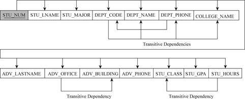
Explanation:
In the above dependency diagram,
- The transitive dependency is,
DEPT_CODE -> (DEPT_NAME, DEPT_PHONE, COLLEGE_NAME)
ADV_OFFICE -> (ADV_BUILDINGS)
STU_HOURS -> (STU_CLASS)
b.
Normalization:
The process used to minimize data redundancy and dependency in a relational database is known as normalization. The database table is divided into two or more tables and defines the relationship between those tables.
Second normal form (2NF):
- The value of all non-primary key attributes should be dependent on the primary key attribute.
- If any attribute is depending on the partial primary key then it should determine the other attributes for an instance of the entity.
- The partial dependencies should be removed from the data model.
Third normal form (3NF):
- The value of any non-primary key attributes will not depend on any other non-primary key attributes.
- If any non-primary key attributes depend on any other non-primary key attribute then it should be moved or deleted.
- It is termed as transitive dependency.
Partial dependency:
A partial dependency exists at that time of an attributes depends only a part of primary key. This dependency is related with 1st normal form.
Transitive dependency:
A transitive dependency exists at that time of an attributes depends on another attribute which is not part of primary key.
Functional dependency:
An association between two attributes or two set of attributes in a same relational database table, which is having some constraints is known as functional dependency.
- In a table one attribute is functionally dependent on another attribute to take one value.
b.
Explanation of Solution
Construct the dependency diagram:
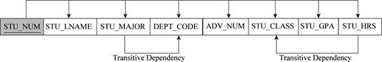
The new dependency diagram is represented by removing all transitive dependencies in STUDENT table.
First table:
The relational schema for first table is given below:
STUDENT(STU_NUM, STU_LNAME, STU_MAJOR, DEPT_CODE, ADVISOR_NUM STU_GPA, STU_HOURS, STU_CLASS)
- Here, “STU_NUM” indicates the primary keys and “ADVISOR_NUM” indicates the foreign key.
- The relation is in third normal form (2NF), since there is transitive dependency in this table.
The representation of dependency diagram in first table is shown below:
Second table:
The relational schema for second table is given below:
MAJOR(MAJOR_CODE, DEPT_CODE, MAJOR_DESCRIPTION)
- Here, “MAJOR_CODE” indicates the primary key.
- The relation is in third normal form (3NF), since there is no transitive dependency and no repeated attributes.
The representation of dependency diagram in second table is shown below:

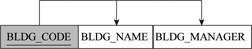
Third table:
The relational schema for third table is given below:
BUILDING(BLDG_CODE, BLDG_NAME, BLDG_MANAGER)
- Here, “BLDG_CODE” indicates the primary key.
- The relation is in third normal form (3NF), since there is no transitive dependency and no repeated attributes.
The representation of dependency diagram in third table is shown below:
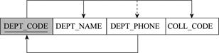
Fourth table:
The relational schema for fourth table is given below:
DEPARTMENT(DEPT_NAME, DEPT_PHONE, COLL_CODE)
- Here, “DEPT_NAME” indicates the primary key.
- The relation is in third normal form (3NF) but it does not meet the BCNF, since there is no transitive dependency and no repeated attributes.
The representation of dependency diagram in fourth table is shown below:
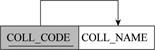
Fifth table:
The relational schema for fifth table is given below:
COLLEGE(COLL_CODE, COLL_NAME)
- Here, “COLL_CODE” indicates the primary key.
- The relation is in third normal form (3NF), since there is no transitive dependency and no repeated attributes.
The representation of dependency diagram in fifth table is shown below:
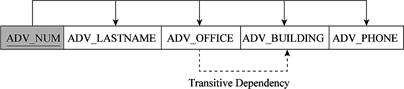
Sixth table:
The relational schema for sixth table is given below:
ADVISOR(ADV_NUM, ADV_LASTNAME, ADV_OFFICE, ADV_BUILDING, ADV_PHONE)
- Here, “ADV_NUM” indicates the primary key.
- The dotted transitive dependency line specifies that dependency is interpretation.
- The relation is in third normal form (2NF), since there is transitive dependency in this table.
The representation of dependency diagram in sixth table is shown below:
c.
Explanation of Solution
The representation of Crow’s Foot Entity Relational Diagram (ERD) is shown below:
The following data model shows the solution for the given question.
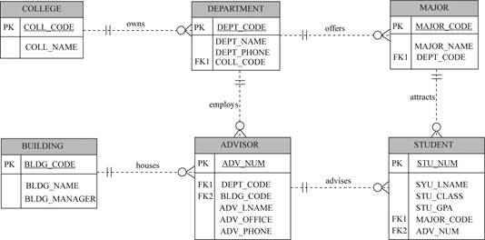
Explanation:
- In the above data model, the college owns more than one department.
- The “COLLEGE” entity contains the “COLL_CODE” and “COLL_NAME” attributes.
- The primary key of “COLL_CODE” entity is “INV_NUM”.
- The “DEPARTMENT” entity contains the “DEPT_CODE”, “DEPT_NAME”, “DEPT_PHONE” and “COLL_CODE” attributes.
- The primary of this entity is “DEPT_CODE”.
- The foreign key of this entity is “COLL_CODE”.
- The “COLLEGE” entity contains the “COLL_CODE” and “COLL_NAME” attributes.
- The department offers more than one major.
- The “MAJOR” entity contains the “MAJOR_CODE”, “MAJOR_NAME”, and “DEPT_CODE” attributes.
- The primary key of “MAJOR_CODE” for this entity.
- The foreign key of this entity is “VEND_CODE”.
- The “MAJOR” entity contains the “MAJOR_CODE”, “MAJOR_NAME”, and “DEPT_CODE” attributes.
- The major attracts more than one student.
- The “STUDENT” entity contains the “STU_NUM”, “STU_LNAME”, “STU_CLASS”, “STU_HOURS”, “STU_GPA”, “MAJOR_CODE”, and “ADV_NUM” attributes.
- The primary key of “STU_NUM” entity.
- The foreign key of this entity is “MAJOR_CODE” and “ADV_NUM”.
- The “STUDENT” entity contains the “STU_NUM”, “STU_LNAME”, “STU_CLASS”, “STU_HOURS”, “STU_GPA”, “MAJOR_CODE”, and “ADV_NUM” attributes.
- The building houses more than one advisor.
- The “ADVISOR” entity contains the “ADV_NUM”, “DEPT_CODE”, “BLDG_CODE”, “ADV_LNAME”, “ADV_OFFICE”, and “ADV_PHONE” attributes.
- The primary key of “ADV_NUM” entity.
- The foreign key of this entity is “DEPT_CODE” and “BLDG_CODE”.
- The “BUILDING” entity contains the “BLDG_CODE”, “BLDG_NAME” and “BLDG_MANAGER” attributes.
- The primary key of “BLDG_CODE” entity.
- The “ADVISOR” entity contains the “ADV_NUM”, “DEPT_CODE”, “BLDG_CODE”, “ADV_LNAME”, “ADV_OFFICE”, and “ADV_PHONE” attributes.
- The advisor advises more than one student.
Want to see more full solutions like this?
Chapter 6 Solutions
Database Systems: Design, Implementation, & Management


- Could you help me to know features of the following concepts: - commercial CA - memory integrity - WMI filterarrow_forwardBriefly describe the issues involved in using ATM technology in Local Area Networksarrow_forwardFor this question you will perform two levels of quicksort on an array containing these numbers: 59 41 61 73 43 57 50 13 96 88 42 77 27 95 32 89 In the first blank, enter the array contents after the top level partition. In the second blank, enter the array contents after one more partition of the left-hand subarray resulting from the first partition. In the third blank, enter the array contents after one more partition of the right-hand subarray resulting from the first partition. Print the numbers with a single space between them. Use the algorithm we covered in class, in which the first element of the subarray is the partition value. Question 1 options: Blank # 1 Blank # 2 Blank # 3arrow_forward
- 1. Transform the E-R diagram into a set of relations. Country_of Agent ID Agent H Holds Is_Reponsible_for Consignment Number $ Value May Contain Consignment Transports Container Destination Ф R Goes Off Container Number Size Vessel Voyage Registry Vessel ID Voyage_ID Tonnagearrow_forwardI want to solve 13.2 using matlab please helparrow_forwarda) Show a possible trace of the OSPF algorithm for computing the routing table in Router 2 forthis network.b) Show the messages used by RIP to compute routing tables.arrow_forward
- using r language to answer question 4 Question 4: Obtain a 95% standard normal bootstrap confidence interval, a 95% basic bootstrap confidence interval, and a percentile confidence interval for the ρb12 in Question 3.arrow_forwardusing r language to answer question 4. Question 4: Obtain a 95% standard normal bootstrap confidence interval, a 95% basic bootstrap confidence interval, and a percentile confidence interval for the ρb12 in Question 3.arrow_forwardusing r languagearrow_forward
- using r languagearrow_forwardusing r language Obtain a bootstrap t confidence interval estimate for the correlation statistic in Example 8.2 (law data in bootstrap).arrow_forwardusing r language Compute a jackknife estimate of the bias and the standard error of the correlation statistic in Example 8.2.arrow_forward
 Database Systems: Design, Implementation, & Manag...Computer ScienceISBN:9781305627482Author:Carlos Coronel, Steven MorrisPublisher:Cengage Learning
 A Guide to SQLComputer ScienceISBN:9781111527273Author:Philip J. PrattPublisher:Course Technology Ptr
 Database Systems: Design, Implementation, & Manag...Computer ScienceISBN:9781285196145Author:Steven, Steven Morris, Carlos Coronel, Carlos, Coronel, Carlos; Morris, Carlos Coronel and Steven Morris, Carlos Coronel; Steven Morris, Steven Morris; Carlos CoronelPublisher:Cengage Learning
 Principles of Information Systems (MindTap Course...Computer ScienceISBN:9781285867168Author:Ralph Stair, George ReynoldsPublisher:Cengage Learning
 Fundamentals of Information SystemsComputer ScienceISBN:9781337097536Author:Ralph Stair, George ReynoldsPublisher:Cengage Learning