
(a)
Find the expression of the voltage across an inductor
(a)
Answer to Problem 1P
The expression of the voltage across an inductor
Explanation of Solution
Given data:
The current through an inductor is
The inductor value is,
Formula used:
Write the general expression to find the voltage across an inductor as,
Here,
L is the value of inductance of the inductor,
Calculation:
Substitute
Conclusion:
Thus, the expression of the voltage across an inductor
(b)
Calculate the power at the inductor terminals at time of
(b)
Answer to Problem 1P
The power at the inductor terminals at time of
Explanation of Solution
Calculation:
Given that
At time
At time
At time
At time
At time
Calculate the voltage at
Write the formula to find the power in an inductor at
Substitute
PSpice simulation:
Use all the above calculated values to give as an input to the PSpice simulation.
From the given information, the current passing through an inductor and here a small resistor is connected in series with inductor to avoid the simulation error.
Draw the circuit as shown in below Figure 1.
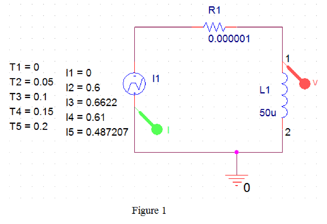
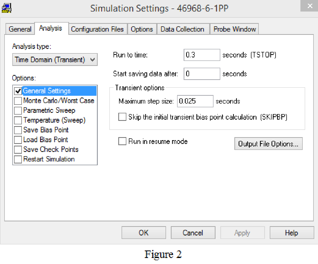
Provide the simulation settings as shown in below Figure 2.
Now, save and run the simulation, then the plot for the input current and voltage across an inductor will be displays as shown in Figure 3.
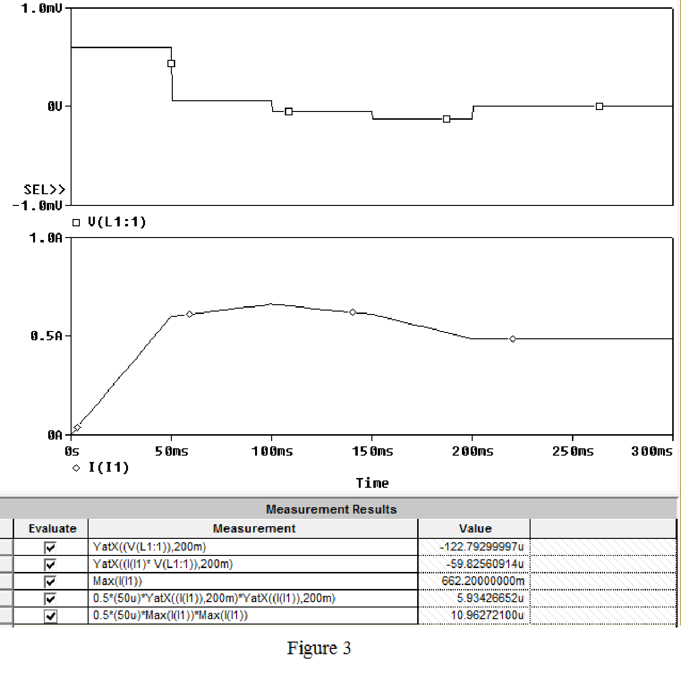
From the Figure 3, the first function is used to read the voltage at
The power calculated at
Conclusion:
Thus, the power at the inductor terminals at time of
(c)
Check whether an inductor is delivering the power or absorbing the power.
(c)
Answer to Problem 1P
An inductor is delivering the power.
Explanation of Solution
Discussion:
The power calculated in an inductor has the negative sign which indicates that the power is delivering by an inductor.
Conclusion:
Thus, an inductor is delivering the power.
(d)
Calculate the energy stored in an inductor in micro joules at
(d)
Answer to Problem 1P
The energy stored in an inductor in at
Explanation of Solution
Discussion:
From the simulation results shown in Part (b), the fourth equation is written to calculate energy stored in an inductor. From the Figure 3, the energy stored in an inductor in at
Conclusion:
Thus, the energy stored in an inductor in at
(e)
Find the maximum energy, and also find the instant of time that occurs.
(e)
Answer to Problem 1P
The maximum energy is
Explanation of Solution
Discussion:
When the current is maximum energy in an inductor also maximum, since the square of current is directly proportional to the energy stored.
From the Figure 3, it is calculated that maximum current as 662.2 mA, that occurs at
Conclusion:
Thus, the maximum energy is
Want to see more full solutions like this?
Chapter 6 Solutions
Electric Circuits. (11th Edition)

- Please show all stepsarrow_forwardA plane wave propagating in the +z direction in medium 1 is normally incident to medium 2 located at the z=0 plane as below. Both mediums are general, characterized by ( ε i, Mi, Ơi ). tot = [ ει μη σ] [ε, μη σε ] Ex Ex tot E₁₂ (z) = Ee Ex z=0 From conservation of energy: P₁AV'(z=0) + Piav'(z=0) = P2av²(z=0). Using the above show for lossless media that: ( 1 - ||²) = (1/M2 )|T|² .arrow_forwardA plane wave propagating in the +z direction in medium 1 is normally incident to medium 2 located at the z=0 plane as below. Both mediums are general, characterized by ( ε i, Hi, σ¡ ). [ ει μη σ] Ex [ ει μη ση ] Ex tot E₁₂ (z) = E'₁e¹² -122 E(z) = Ee+ E₁₁₁² E₁x z=0 1. Specify the electric field reflection coefficient г and transmission coefficient T: E ΓΔ E E TA EL 2. Show that T=1+г. Can the transmitted electric field amplitude in region 2 be LARGER than the incident electric field amplitude? 3. Determine expressions for P₁AV'(z), PIAV'(z) and P2AV'(z) (note the sign for the reflected power direction should be (-z).arrow_forward
- 2) In the ideal transformer circuit shown below find Vo and the complex power supplied by the source. 292 www b 1:4 16 Ω ww + + 240/0° V rms -12492arrow_forward3) In the ideal autotransformer circuit shown below find 11, 12 and lo. Find the average power delivered to the load. (hint: write KVL for both sides) 20/30° V(+ 2-1602 200 turns V₂ 10 + j40 Ω 80 turns V₁arrow_forward1) Find Vo in the following circuit. Assume the mesh currents are clockwise. ΠΩ Ω ΖΩ ww 1Ω ww 24/0° (± 6 Ω j4 Ω 1Ω +arrow_forward
- Please show all stepsarrow_forward11-3) similar to Lathi & Ding, Prob. P.6.8-1 Consider the carrier modulator shown in the figure below, which transmits a binary carrier signal. The baseband generator uses polar NRZ signaling with rectangular pulses. The data rate is 8 Mbit/s. (a) If the modulator generates a binary PSK signal, what is the bandwidth of the modulated output? (b) If the modulator generates FSK with the difference fel - fco = 6 MHz (cf. Fig 6.32c), determine the modulated signal bandwidth. Binary data source Baseband signal generator Modulated output Modulator N-E---arrow_forwardSolve this problem and show all of the workarrow_forward
- Q3: Why is the DRAM cell design simpler but slower than SRAM?arrow_forward5052 ми a JXL 000 +2 16s (wt) bi jxc M 100♫ ZL. Find the Value of XL & X c if the Circuit trans for Max. Power to (ZL).arrow_forwardChoose the best answer for each: 1. What does SRAM use to store data? 。 a) Capacitors ob) Latches 。 c) Flip-flops od) Transistors 2. Which RAM type requires refreshing? o a) SRAM ob) DRAM 。 c) ROM od) Flash 3. What type of memory retains data only while power is on? a) ROM 。 b) EEPROM o c) DRAM od) Flash 4. How many addresses can a 15-bit address bus handle? o a) 32k • b) 64k o c) 16k od) lk 5. What operation occurs when data is copied out of memory without erasing? oa) Write ob) Read o c) Refresh o d) Load 6. DRAM cells store bits using: a) Flip-flops 。 b) Capacitors c) Diodes od) Resistors 7. The cache located inside the CPU is: 。 a) L2 cache o b) LI cache °c) ROM od) HDD 8. SDRAM is synchronized with: o a) Cache ob) Data Bus c) System Clock od) Hard Disk 9. The bus that carries commands is called: o a) Data Bus b) Control Bus o c) Address Bus o d) Logic Bus 10. What is the main use of SRAM? o Disk storage o Cache o Main memory o Registers 11. The smallest addressable unit in…arrow_forward
 Introductory Circuit Analysis (13th Edition)Electrical EngineeringISBN:9780133923605Author:Robert L. BoylestadPublisher:PEARSON
 Delmar's Standard Textbook Of ElectricityElectrical EngineeringISBN:9781337900348Author:Stephen L. HermanPublisher:Cengage Learning
 Programmable Logic ControllersElectrical EngineeringISBN:9780073373843Author:Frank D. PetruzellaPublisher:McGraw-Hill Education
 Fundamentals of Electric CircuitsElectrical EngineeringISBN:9780078028229Author:Charles K Alexander, Matthew SadikuPublisher:McGraw-Hill Education
 Electric Circuits. (11th Edition)Electrical EngineeringISBN:9780134746968Author:James W. Nilsson, Susan RiedelPublisher:PEARSON
 Engineering ElectromagneticsElectrical EngineeringISBN:9780078028151Author:Hayt, William H. (william Hart), Jr, BUCK, John A.Publisher:Mcgraw-hill Education,