
Statics and Mechanics of Materials (5th Edition)
5th Edition
ISBN: 9780134382593
Author: Russell C. Hibbeler
Publisher: PEARSON
expand_more
expand_more
format_list_bulleted
Videos
Textbook Question
Chapter 5.5, Problem 35P
Determine the force P required to hold the 150-kg crate in equilibrium.
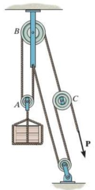
Prob. 5-35
Expert Solution & Answer
Want to see the full answer?
Check out a sample textbook solution
Students have asked these similar questions
The resistance R and load effect S for a given failure mode are statistically independent random variables
with marginal PDF's
1
fR (r) =
0≤r≤100
100'
fs(s)=0.05e-0.05s
(a) Determine the probability of failure by computing the probability content of the failure domain defined
as {r
Please solve this problem as soon as possible My ID# 016948724
The gears shown in the figure have a diametral pitch of 2 teeth per inch and a 20° pressure angle.
The pinion rotates at 1800 rev/min clockwise and transmits 200 hp through the idler pair to gear
5 on shaft c. What forces do gears 3 and 4 transmit to the idler shaft?
TS
I
y
18T
32T
This
a
12
x
18T
C
48T
5
Chapter 5 Solutions
Statics and Mechanics of Materials (5th Edition)
Ch. 5.3 - In each ease, calculate the support reactions and...Ch. 5.3 - Identify the zero-force members in each truss....Ch. 5.3 - Determine the force in each member of the truss...Ch. 5.3 - Determine the force in each member of the truss...Ch. 5.3 - Determine the force in each member of the truss...Ch. 5.3 - Determine the greatest load P that can be applied...Ch. 5.3 - Identify the zero-force members in the truss....Ch. 5.3 - Determine the force in each member of the truss...Ch. 5.3 - Determine the force in each member of the truss...Ch. 5.3 - Determine the force in each member of the truss...
Ch. 5.3 - Determine the force in each member of the truss...Ch. 5.3 - Determine the force in each member of the truss...Ch. 5.3 - Determine the force in each member of the truss,...Ch. 5.3 - Determine the force in each member of the truss,...Ch. 5.3 - Determine the force in each member of the truss...Ch. 5.3 - Determine the force in each member of the truss in...Ch. 5.3 - Members AB and BC can each support a maximum...Ch. 5.3 - Members AB and BC can each support a maximum...Ch. 5.3 - Determine the force in each member of the truss...Ch. 5.3 - If the maximum force that any member can support...Ch. 5.3 - Determine the force in each member of the truss...Ch. 5.3 - Determine the force in each member of the truss...Ch. 5.3 - Determine the force in each member of the truss...Ch. 5.3 - Determine the force in each member of the truss...Ch. 5.4 - Determine the force in members BC, CF, and FE and...Ch. 5.4 - Determine the force in members LK, KC, and CD of...Ch. 5.4 - Determine the force in members KJ, KD, and CD of...Ch. 5.4 - Determine the force in members EF, CF, and BC of...Ch. 5.4 - Determine the force in members GF, GD, and CD of...Ch. 5.4 - Determine the force in members DC, HI, and JI of...Ch. 5.4 - Determine the force in members DC, HC and HI of...Ch. 5.4 - Determine the force in members ED, EH, and GH of...Ch. 5.4 - Determine the force in members HG, HE, and DE of...Ch. 5.4 - Determine the force in members CD, HI, and CH of...Ch. 5.4 - Determine the force in members CD, CJ, KJ, and DJ...Ch. 5.4 - Prob. 22PCh. 5.4 - The Howe truss is subjected to the loading shown....Ch. 5.4 - The Howe truss is subjected to the loading shown....Ch. 5.4 - Determine the force in members EF, CF, and BC, and...Ch. 5.4 - Determine the force in members AF, BF, and BC, and...Ch. 5.4 - Prob. 27PCh. 5.4 - Determine the force in members BC, BE, and EF of...Ch. 5.4 - Prob. 29PCh. 5.4 - Determine the force in members CD, CF, and CG and...Ch. 5.4 - Determine the force developed in members FE, EB,...Ch. 5.5 - In each ease, identify any two-force members, and...Ch. 5.5 - F5-13. Determine the force P needed to hold the...Ch. 5.5 - Determine the horizontal and vertical components...Ch. 5.5 - If a 100-N force is applied to the handles of the...Ch. 5.5 - Determine the horizontal and vertical components...Ch. 5.5 - Determine the force P required to hold the 100-lb...Ch. 5.5 - In each case, determine the force P required to...Ch. 5.5 - Determine the force P required to hold the 50-kg...Ch. 5.5 - Determine the force P required to hold the 150-kg...Ch. 5.5 - Determine the reactions at the supports A, C, and...Ch. 5.5 - Determine the resultant force at pins A, B, and C...Ch. 5.5 - Determine the reactions at the supports at A, E,...Ch. 5.5 - The wall crane supports a load of 700 lb....Ch. 5.5 - The wall crane supports a load of 700 lb....Ch. 5.5 - Determine the horizontal and vertical components...Ch. 5.5 - Determine the force in members FD and DB of the...Ch. 5.5 - Determine the force that the smooth 20-kg cylinder...Ch. 5.5 - The three power lines exert the forces shown on...Ch. 5.5 - The pumping unit is used to recover oil. When the...Ch. 5.5 - Determine the force that the jaws J of the metal...Ch. 5.5 - Prob. 47PCh. 5.5 - Prob. 48PCh. 5.5 - Prob. 49PCh. 5.5 - Determine the force created in the hydraulic...Ch. 5.5 - The hydraulic crane is used to lift the 1400-lb...Ch. 5.5 - Determine force P on the cable if the spring is...Ch. 5.5 - Prob. 53PCh. 5.5 - Prob. 54PCh. 5.5 - Prob. 55PCh. 5.5 - Determine the force P on the cable if the spring...Ch. 5.5 - Prob. 57PCh. 5.5 - Prob. 58PCh. 5.5 - Prob. 59PCh. 5.5 - Prob. 60PCh. 5.5 - The platform scale consists of a combination of...Ch. 5 - All the problems solutions must include FBDs....Ch. 5 - Determine the force in each member of the truss...Ch. 5 - Determine the force in member GJ and GC of the...Ch. 5 - Determine the force in members GF, FB, and BC of...Ch. 5 - Prob. 5RPCh. 5 - Determine the horizontal and vertical components...Ch. 5 - Prob. 7RPCh. 5 - Determine the resultant forces at pins B and C on...
Knowledge Booster


Learn more about
Need a deep-dive on the concept behind this application? Look no further. Learn more about this topic, mechanical-engineering and related others by exploring similar questions and additional content below.Similar questions
- Question 1. Draw 3 teeth for the following pinion and gear respectively. The teeth should be drawn near the pressure line so that the teeth from the pinion should mesh those of the gear. Drawing scale (1:1). Either a precise hand drawing or CAD drawing is acceptable. Draw all the trajectories of the involute lines and the circles. Specification: 18tooth pinion and 30tooth gear. Diameter pitch=P=6 teeth /inch. Pressure angle:20°, 1/P for addendum (a) and 1.25/P for dedendum (b). For fillet, c=b-a.arrow_forward5. The figure shows a gear train. There is no friction at the bearings except for the gear tooth forces. The material of the milled gears is steel having a Brinell hardness of 170. The input shaft speed (n2) is 800 rpm. The face width and the contact angle for all gears are 1 in and 20° respectively. In this gear set, the endurance limit (Se) is 15 kpsi and nd (design factor) is 2. (a) Find the revolution speed of gear 5. (b) Determine whether each gear satisfies the design factor of 2.0 for bending fatigue. (c) Determine whether each gear satisfies the design factor of 2.0 for surface fatigue (contact stress). (d) According to the computation results of the questions (b) and (c), explain the possible failure mechanisms for each gear. N4=28 800rpm N₁=43 N5=34 N₂=14 P(diameteral pitch)=8 for all gears Coupled to 2.5hp motorarrow_forward1. The rotating steel shaft is simply supported by bearings at points of B and C, and is driven by a spur gear at D, which has a 6-in pitch diameter. The force F from the drive gear acts at a pressure angle of 20°. The shaft transmits a torque to point A of TA =3000 lbĘ in. The shaft is machined from steel with Sy=60kpsi and Sut=80 kpsi. (1) Draw a shear force diagram and a bending moment diagram by F. According to your analysis, where is the point of interest to evaluate the safety factor among A, B, C, and D? Describe the reason. (Hint: To find F, the torque Tд is generated by the tangential force of F (i.e. Ftangential-Fcos20°) When n=2.5, K=1.8, and K₁ =1.3, determine the diameter of the shaft based on (2) static analysis using DE theory (note that fatigue stress concentration factors need to be used for this question because the loading condition is fatigue) and (3) a fatigue analysis using modified Goodman. Note) A standard diameter is not required for the questions. 10 in Darrow_forward
- 3 N2=28 P(diametral pitch)=8 for all gears Coupled to 25 hp motor N3=34 Full depth spur gears with pressure angle=20° N₂=2000 rpm (1) Compute the circular pitch, the center-to-center distance, and base circle radii. (2) Draw the free body diagram of gear 3 and show all the forces and the torque. (3) In mounting gears, the center-to-center distance was reduced by 0.1 inch. Calculate the new values of center-to-center distance, pressure angle, base circle radii, and pitch circle diameters. (4)What is the new tangential and radial forces for gear 3? (5) Under the new center to center distance, is the contact ratio (mc) increasing or decreasing?arrow_forward2. A flat belt drive consists of two 4-ft diameter cast-iron pulleys spaced 16 ft apart. A power of 60 hp is transmitted by a pulley whose speed is 380 rev/min. Use a service factor (Ks) pf 1.1 and a design factor 1.0. The width of the polyamide A-3 belt is 6 in. Use CD=1. Answer the following questions. (1) What is the total length of the belt according to the given geometry? (2) Find the centrifugal force (Fc) applied to the belt. (3) What is the transmitted torque through the pulley system given 60hp? (4) Using the allowable tension, find the force (F₁) on the tight side. What is the tension at the loose side (F2) and the initial tension (F.)? (5) Using the forces, estimate the developed friction coefficient (f) (6) Based on the forces and the given rotational speed, rate the pulley set. In other words, what is the horse power that can be transmitted by the pulley system? (7) To reduce the applied tension on the tight side, the friction coefficient is increased to 0.75. Find out the…arrow_forwardThe tooth numbers for the gear train illustrated are N₂ = 24, N3 = 18, №4 = 30, №6 = 36, and N₁ = 54. Gear 7 is fixed. If shaft b is turned through 5 revolutions, how many turns will shaft a make? a 5 [6] barrow_forward
- Please do not use any AI tools to solve this question. I need a fully manual, step-by-step solution with clear explanations, as if it were done by a human tutor. No AI-generated responses, please.arrow_forwardPlease do not use any AI tools to solve this question. I need a fully manual, step-by-step solution with clear explanations, as if it were done by a human tutor. No AI-generated responses, please.arrow_forwardCE-112 please solve this problem step by step and give me the correct answerarrow_forward
arrow_back_ios
SEE MORE QUESTIONS
arrow_forward_ios
Recommended textbooks for you
 International Edition---engineering Mechanics: St...Mechanical EngineeringISBN:9781305501607Author:Andrew Pytel And Jaan KiusalaasPublisher:CENGAGE L
International Edition---engineering Mechanics: St...
Mechanical Engineering
ISBN:9781305501607
Author:Andrew Pytel And Jaan Kiusalaas
Publisher:CENGAGE L
Mechanical SPRING DESIGN Strategy and Restrictions in Under 15 Minutes!; Author: Less Boring Lectures;https://www.youtube.com/watch?v=dsWQrzfQt3s;License: Standard Youtube License