
Videos
A piston–cylinder device initially contains 1.2 kg of air at 700 kPa and 200°C. At this state, the piston is touching on a pair of stops. The mass of the piston is such that 600-kPa pressure is required to move it. A valve at the bottom of the tank is opened, and air is withdrawn from the cylinder. The valve is closed when the volume of the cylinder decreases to 80 percent of the initial volume. If it is estimated that 40 kJ of heat is lost from the cylinder, determine (a) the final temperature of the air in the cylinder, (b) the amount of mass that has escaped from the cylinder, and (c) the work done. Use constant specific heats at the average temperature.
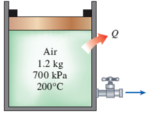
FIGURE P5–183
(a)
The final temperature of air in the cylinder.
Answer to Problem 185RP
The final temperature of air in the cylinder is
Explanation of Solution
Write the equation of mass balance.
Here, the inlet mass is
The change in mass of the system for the control volume is expressed as,
Here, the suffixes 1 and 2 indicates the initial and final states of the system.
Consider the piston-cylinder as the control volume. Initially the cylinder is filled with air and the valve is in closed position, further no other mass is allowed to enter the cylinder. Hence, the inlet mass is neglected i.e.
Rewrite the Equation (I) as follows.
Write the formula for initial volume of air present in the cylinder.
Here, the mass of air is
Write the formula for mass of air present in the cylinder at final state.
Here, the subscript 2 indicates the final state.
Write the energy balance equation.
Here, the heat transfer is
The pressure of
The Equation (V) reduced as follows.
Write the formula for boundary work done on the cylinder.
Here, the pressure required to move the piston is
The enthalpy and internal energy in terms of temperature and specific heats are expressed as follows.
Rewrite the Equation (VI) as follows.
The temperature of the air while exiting the cylinder is considered as the average temperature of initial and final temperatures.
Refer Table A-1, “Molar mass, gas constant, and critical-point properties”.
The gas constant
Refer Table A-2b, “Ideal-gas specific heats of various common gases”.
The specific heat at constant pressure
Conclusion:
Substitute
It is given that the final volume is 80 % of initial volume.
Substitute
Substitute
Substitute
Substitute
Use Engineering Equation Solver (EES) or online calculator to solve the Equation (X) and obtain the value of
Thus, the final temperature of air in the cylinder is
(b)
The amount of mass escaped from the cylinder.
Answer to Problem 185RP
The amount of mass escaped from the cylinder is
Explanation of Solution
The amount of mass escaped from the cylinder is nothing but the mass of air vented out until final state i.e.
Refer Equation (II) and (IX).
Conclusion:
Substitute
Thus, the amount of mass escaped from the cylinder is
(c)
The work done.
Answer to Problem 185RP
The amount of mass escaped from the cylinder is
Explanation of Solution
The work done is nothing but the work done on the piston to move it i.e. boundary work
Refer part (a).
Thus, the work done is
Want to see more full solutions like this?
Chapter 5 Solutions
EBK THERMODYNAMICS: AN ENGINEERING APPR


- A tensile specimen made of hot-rolled AISI 1020 steel is loaded to point corresponding to a strain of 40%. 60 Su = 66 ksi Stress σ (ksi) S₁ = 39 ksi 40 Se = 36 ksi Hot-rolled 1020 steel 20 0 10 20 30 40 50 60 70 80 90 100 110 120 130 140 150 160 Strain € (%) 0 1.1 1.2 1.3 1.4 1.5 1.6 1.7 1.8 1.9 2.0 2.1 2.2 2.3 2.4 2.5 2.6 Area ratio R 0.1 0.2 0.3 0.4 0.5 Area reduction A, What value of area ratio is applicable to this location? 0.6arrow_forwardA tensile specimen made of hot-rolled AISI 1020 steel is loaded to point corresponding to a strain of 43%. 60 Su = 66 ksi Stress σ (ksi) 20 Sy = 39 ksi Se = 36 ksi Hot-rolled 1020 steel F 0 10 20 30 40 50 60 70 80 90 100 110 120 130 140 150 160 Strain € (%) 0 1.1 1.2 1.3 1.4 1.5 1.6 1.7 1.8 1.9 2.0 2.1 2.2 2.3 2.4 2.5 2.6 Area ratio R 0.1 0.2 0.3 0.4 0.5 Area reduction A, What value of area reduction is applicable to this location? 0.6arrow_forwardTable of Measurements and Results: Reading m/s Ji- a (wh Nu h Re Nu Error% (C) (°C) 2 1 Discussion: 1-Estimate the heat transfer and experimental value of the heat transfer coefficient hex with its unit and Nusselt number Nu expl 2- Find the percentage error for the value of the experimental Nusselt number. 3-Draw the graph showing a relationship between the temperatures difference (T-T) and theoretical and experimental value of Nusselt number. 4-The forced convection heat transfer coefficient of a plate depends on which of the following: a-gravity. b-velocity of fluid. e-conductivity of fluid. d-conductivity of plate material. Experiment: Internal Forced convenction Heat trovate on now through t objectives. Study the convection heat transfer of air flow through stage Calculations. Q & (T-T) Vary Re Q. heup A (TT) (T. Te-T ASPL Nep Re 117 RITT 14 ' 14arrow_forward
- If AE = 1.6 m, ED = CD = 1.9 m and F = 3.1 kN, then find the magnitude of the force acting in EB. B 30° 30° C E D ED m DC m ♥F KNarrow_forwardAssume multiple single degree of freedom systems with natural periods T ∈ [0.05, 2.00] seconds with in- crement of period dT = 0.05 seconds. Assume three cases of damping ratio: Case (A) ξ = 0%; Case (B) ξ = 2%; Case (C) ξ = 5%. The systems are initially at rest. Thus, the initial conditions are u(t = 0) = 0 and ̇u(t = 0) = 0. The systems are subjected to the base acceleration that was provided in the ElCentro.txt file (i.e., first column). For the systems in Case (A), Case (B), and Case (C) and for each natural period compute the peak acceleration, peak velocity, and peak displacement responses to the given base excitation. Please, use the Newmark method for β = 1/4 (average acceleration) to compute the responses. Create three plots with three lines in each plot. The first plot will have the peak accelerations in y-axis and the natural period of the system in x-axis. The second plot will have the peak velocities in y-axis and the natural period of the system in x-axis. The third plot…arrow_forwardDetermine the resultant stress at points P and Q.arrow_forward
- For the notched specimen with h = 0.13 m and r =11 mm, calculate the nominal stress for F=5 kN. F h F 25 mm Please submit your answer in the units of MPa.arrow_forwardA tensile specimen made of hot-rolled AISI 1020 steel is loaded to point corresponding to a strain of 49%. 60 Su = 66 ksi Stress σ (ksi) Sy = 39 ksi 400B Se = 36 ksi Hot-rolled 1020 steel 20 F 0 0 10 20 30 40 50 60 70 80 90 100 110 120 130 140 150 160 Strain € (%) 0 1.1 1.2 1.3 1.4 1.5 1.6 1.7 1.8 1.9 2.0 2.1 2.2 2.3 2.4 2.5 2.6 Area ratio R 0.1 0.2 0.3 0.4 0.5 Area reduction A, What value of Su is applicable to this location? 0.6arrow_forwardA tensile specimen made of hot-rolled AISI 1020 steel is loaded to point corresponding to a strain of 40%. 60 Su = 66 ksi Stress σ (ksi) 40 20 Sy= = 39 ksi Se = 36 ksi Hot-rolled 1020 steel F | G | H 0 10 20 30 40 50 60 0 70 80 90 100 110 120 130 140 150 160 Strain € (%) ☐ T 1.1 1.2 1.3 1.4 1.5 1.6 1.7 1.8 1.9 2.0 2.1 2.2 2.3 2.4 2.5 2.6 Area ratio R 0.1 0.2 0.3 0.4 0.5 Area reduction A, What value of Sy is applicable to this location? 0.6arrow_forward
- A vertical .2m by .2m square plate is exposed to saturated water vapor at atmospheric pressure. If the surface temperature is 80 degrees C and the flow is laminar, estimate the loal heat transfer coefficents at the middles and at the bottom of the plate.arrow_forwardA transformer that is 10 cm long, 6.2 cm wide, and 5 cm high is to be cooled by attaching a 10 cm by 6.2 cm wide polished aluminum heat sink(emissivity=.03) to its top surface. The heat sink has seven fins, which are 5 mm high, 2mm thick, and 10 cm long. A fan blows air at 25 degrees C parallel to the passages between the fins. The heat sink is to dissipate 12W of heat, and the base temp of the ehat sink is not to exceed 60 degrees C. Assuming the fins and the base plate to be nearly isothermal and the radiation heat transfer to be negligible, determine the minimum free-stream velocity the fan needs to supply to avoid overheating. Assume the flow is laminar over the entire finned surface of the transformer.arrow_forwardI need a mechanical engineering expert to solve this question,no Ai pleasearrow_forward
 Elements Of ElectromagneticsMechanical EngineeringISBN:9780190698614Author:Sadiku, Matthew N. O.Publisher:Oxford University Press
 Mechanics of Materials (10th Edition)Mechanical EngineeringISBN:9780134319650Author:Russell C. HibbelerPublisher:PEARSON
 Thermodynamics: An Engineering ApproachMechanical EngineeringISBN:9781259822674Author:Yunus A. Cengel Dr., Michael A. BolesPublisher:McGraw-Hill Education
 Control Systems EngineeringMechanical EngineeringISBN:9781118170519Author:Norman S. NisePublisher:WILEY
 Mechanics of Materials (MindTap Course List)Mechanical EngineeringISBN:9781337093347Author:Barry J. Goodno, James M. GerePublisher:Cengage Learning
 Engineering Mechanics: StaticsMechanical EngineeringISBN:9781118807330Author:James L. Meriam, L. G. Kraige, J. N. BoltonPublisher:WILEY