Understanding Motor Controls
4th Edition
ISBN: 9781337798686
Author: Stephen L. Herman
Publisher: Delmar Cengage Learning
expand_more
expand_more
format_list_bulleted
Concept explainers
Textbook Question
Chapter 54, Problem 8RQ
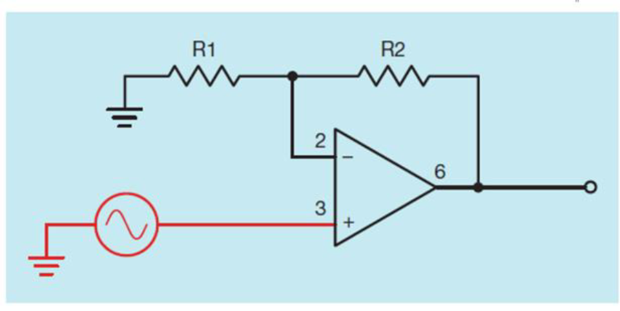
Refer to Figure 54–8. If resistor R1 is 200 ohms and resistor R2 is 10 kilohms, what is the gain of the amplifier?

Figure 54–8 Noninverting amplifier connection.
Expert Solution & Answer
Want to see the full answer?
Check out a sample textbook solution
Students have asked these similar questions
3
N2=28
P(diametral pitch)=8 for all gears
Coupled to 25 hp motor
N3=34
Full depth spur gears with pressure angle=20°
N₂=2000 rpm
(1) Compute the circular pitch, the center-to-center distance, and base circle radii.
(2) Draw the free body diagram of gear 3 and show all the forces and the torque.
(3) In mounting gears, the center-to-center distance was reduced by 0.1 inch.
Calculate the new values of center-to-center distance, pressure angle, base circle radii,
and pitch circle diameters.
(4)What is the new tangential and radial forces for gear 3?
(5) Under the new center to center distance, is the contact ratio (mc) increasing or
decreasing?
2. A flat belt drive consists of two 4-ft diameter cast-iron pulleys spaced 16 ft apart.
A power of 60 hp is transmitted by a pulley whose speed is 380 rev/min. Use a
service factor (Ks) pf 1.1 and a design factor 1.0. The width of the polyamide A-3
belt is 6 in. Use CD=1. Answer the following questions.
(1) What is the total length of the belt according to the given geometry?
(2) Find the centrifugal force (Fc) applied to the belt.
(3) What is the transmitted torque through the pulley system given 60hp?
(4) Using the allowable tension, find the force (F₁) on the tight side. What is the
tension at the loose side (F2) and the initial tension (F.)?
(5) Using the forces, estimate the developed friction coefficient (f)
(6) Based on the forces and the given rotational speed, rate the pulley set. In other
words, what is the horse power that can be transmitted by the pulley system?
(7) To reduce the applied tension on the tight side, the friction coefficient is
increased to 0.75. Find out the…
The tooth numbers for the gear train illustrated are N₂ = 24, N3 = 18, №4 = 30, №6 = 36, and
N₁ = 54. Gear 7 is fixed. If shaft b is turned through 5 revolutions, how many turns will shaft a make?
a
5
[6]
b
Chapter 54 Solutions
Understanding Motor Controls
Ch. 54 - Prob. 1RQCh. 54 - Prob. 2RQCh. 54 - Prob. 3RQCh. 54 - Prob. 4RQCh. 54 - Prob. 5RQCh. 54 - Prob. 6RQCh. 54 - Name two effects of negative feedback.Ch. 54 - Refer to Figure 548. If resistor R1 is 200 ohms...Ch. 54 - Refer to Figure 54–9. If resistor R1 is 470 ohms...Ch. 54 - What is the purpose of the hysteresis loop when...
Knowledge Booster
Learn more about
Need a deep-dive on the concept behind this application? Look no further. Learn more about this topic, mechanical-engineering and related others by exploring similar questions and additional content below.Similar questions
- Please do not use any AI tools to solve this question. I need a fully manual, step-by-step solution with clear explanations, as if it were done by a human tutor. No AI-generated responses, please.arrow_forwardPlease do not use any AI tools to solve this question. I need a fully manual, step-by-step solution with clear explanations, as if it were done by a human tutor. No AI-generated responses, please.arrow_forwardCE-112 please solve this problem step by step and give me the correct answerarrow_forward
- CE-112 please solve this problem step by step and give me the correct asnwerarrow_forwardthis is an old practice exam, the answer is Ax = -4, Ay = -12,Az = 32.5, Bx= 34, Bz = 5, By = 0 but how?arrow_forwardThis is an old practice exam, the answer is Ax = Az = 0, Ay = 2000, TDE = 4750, Cx = 2000, Cy = 2000, Cz = -800 but how?arrow_forward
- this is an old practice exam, the answer is Fmin = 290.5lb but howarrow_forwardThis is an exam review question. The answer is Pmin = 622.9 lb but whyarrow_forwardPlease do not use any AI tools to solve this question. I need a fully manual, step-by-step solution with clear explanations, as if it were done by a human tutor. No AI-generated responses, please.arrow_forward
arrow_back_ios
SEE MORE QUESTIONS
arrow_forward_ios
Recommended textbooks for you
 Understanding Motor ControlsMechanical EngineeringISBN:9781337798686Author:Stephen L. HermanPublisher:Delmar Cengage Learning
 Refrigeration and Air Conditioning Technology (Mi...Mechanical EngineeringISBN:9781305578296Author:John Tomczyk, Eugene Silberstein, Bill Whitman, Bill JohnsonPublisher:Cengage Learning
 Electrical Transformers and Rotating MachinesMechanical EngineeringISBN:9781305494817Author:Stephen L. HermanPublisher:Cengage Learning
 Automotive Technology: A Systems Approach (MindTa...Mechanical EngineeringISBN:9781133612315Author:Jack Erjavec, Rob ThompsonPublisher:Cengage Learning
 Automotive TechnologyMechanical EngineeringISBN:9781337794213Author:ERJAVEC, Jack.Publisher:Cengage,

Understanding Motor Controls
Mechanical Engineering
ISBN:9781337798686
Author:Stephen L. Herman
Publisher:Delmar Cengage Learning

Refrigeration and Air Conditioning Technology (Mi...
Mechanical Engineering
ISBN:9781305578296
Author:John Tomczyk, Eugene Silberstein, Bill Whitman, Bill Johnson
Publisher:Cengage Learning

Electrical Transformers and Rotating Machines
Mechanical Engineering
ISBN:9781305494817
Author:Stephen L. Herman
Publisher:Cengage Learning

Automotive Technology: A Systems Approach (MindTa...
Mechanical Engineering
ISBN:9781133612315
Author:Jack Erjavec, Rob Thompson
Publisher:Cengage Learning

Automotive Technology
Mechanical Engineering
ISBN:9781337794213
Author:ERJAVEC, Jack.
Publisher:Cengage,
Ch 2 - 2.2.2 Forced Undamped Oscillation; Author: Benjamin Drew;https://www.youtube.com/watch?v=6Tb7Rx-bCWE;License: Standard youtube license