
Mechanics of Materials Plus Mastering Engineering with Pearson eText - Access Card Package (10th Edition)
10th Edition
ISBN: 9780134518121
Author: Russell C. Hibbeler
Publisher: PEARSON
expand_more
expand_more
format_list_bulleted
Concept explainers
Videos
Textbook Question
thumb_up100%
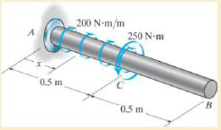
Chapter 5.4, Problem 5.50P
Determine the absolute maximum shear stress in the shaft and plot a graph of the angle of twist of the shaft in radians versus x.
Expert Solution & Answer
Want to see the full answer?
Check out a sample textbook solution
Students have asked these similar questions
Design Description: Fresh water tank, immersed in an oil tank.a) Water tank:a. Shape: Cylindricalb. Radius: 1 meterc. Height: 3 metersd. Bottom airlock: 0.2m x 0.2m.
b) Oil tank:a. Shape: cylindricalb. Radius: 4 metersc. Oil density: 850 kg/m³
Determine:a) The pressure experienced by an airlock at the bottom of the tank with water.b) The force and direction necessary to open the lock, suppose the lock weighs 20 Newtons, suppose the lock opens outwards.
The image is for illustrative purposes, the immersed cylinder does not reach the bottom
Need help!
need help understanding?
Chapter 5 Solutions
Mechanics of Materials Plus Mastering Engineering with Pearson eText - Access Card Package (10th Edition)
Ch. 5.3 - Determine the internal torque at each section and...Ch. 5.3 - Determine the. internal torque at each section and...Ch. 5.3 - The solid and hollow shafts are each subjected to...Ch. 5.3 - The motor delivers 10 hp to the shaft. If it...Ch. 5.3 - The solid circular shaft is subjected to an...Ch. 5.3 - The hollow circular shaft is subjected to an...Ch. 5.3 - The shaft is hollow from A to B and solid from B...Ch. 5.3 - Determine the maximum shear stress in the...Ch. 5.3 - Determine the maximum shear stress in the shaft at...Ch. 5.3 - Determine the shear stress a: point A on the...
Ch. 5.3 - The solid 50-mm-diameter shaft is subjected to the...Ch. 5.3 - The gear motor can develop 3 hp when it turns at...Ch. 5.3 - The solid shaft of radius r is subjected to a...Ch. 5.3 - The solid shaft of radius r is subjected to a...Ch. 5.3 - A shaft is made of an aluminum alloy having an...Ch. 5.3 - The copper pipe has an outer diameter of 40 mm and...Ch. 5.3 - The copper pipe has an outer diameter of 2.50 in....Ch. 5.3 - The solid aluminum shaft has a diameter of 50 mm...Ch. 5.3 - The solid aluminum shaft has a diameter of 50 mm....Ch. 5.3 - The solid 30-mm-diameter shaft is used to transmit...Ch. 5.3 - The solid shaft is fixed to the support at C and...Ch. 5.3 - The link acts as part of the elevator control for...Ch. 5.3 - The assembly consists of two sections of...Ch. 5.3 - The shaft has an outer diameter of 100 mm and an...Ch. 5.3 - The shaft has an outer diameter of 100 mm and an...Ch. 5.3 - A steel tube having an outer diameter of 2.5 in....Ch. 5.3 - If the gears are subjected to the torques shown,...Ch. 5.3 - If the gears are subjected to the torques shown,...Ch. 5.3 - The rod has a diameter of 1 in. and a weight of 10...Ch. 5.3 - The rod has a diameter of 1 in. and a weight of 15...Ch. 5.3 - The copper pipe has an outer diameter of 3 in. and...Ch. 5.3 - The copper pipe has an outer diameter of 3 in. and...Ch. 5.3 - The 60-mm-diameter solid shaft is subjected to the...Ch. 5.3 - The 60-mm-diameter solid shaft is subjected to the...Ch. 5.3 - The solid shaft is subjected to the distributed...Ch. 5.3 - The 60-mm-diameter solid shaft is subjected to the...Ch. 5.3 - The solid shaft is subjected to the distributed...Ch. 5.3 - The pipe has an outer radius r0 and inner radius...Ch. 5.3 - The drive shaft AB of an automobile is made of a...Ch. 5.3 - The drive shaft AB of an automobile is to be...Ch. 5.3 - Prob. 5.29PCh. 5.3 - The motor delivers 50 hp while turning at a...Ch. 5.3 - The solid steel shaft AC has a diameter of 25 mm...Ch. 5.3 - The pump operates using the motor that has a power...Ch. 5.3 - The gear motor can develop 110 hp when it turns at...Ch. 5.3 - The gear motor can develop 110 hp when it turns at...Ch. 5.3 - The gear motor can develop 14 hp when it turns at...Ch. 5.3 - The gear motor can develop 2 hp when it turns at...Ch. 5.3 - The 6-hp reducer motor can turn at 1200 rev/min....Ch. 5.3 - The 6-hp reducer motor can turn at 1200 rev/min....Ch. 5.3 - Prob. 5.39PCh. 5.3 - Prob. 5.40PCh. 5.3 - The A-36 steel tubular shaft is 2 m long and has...Ch. 5.3 - Prob. 5.42PCh. 5.3 - The solid shaft has a linear taper from rA at one...Ch. 5.3 - The 1-in.-diameter bent rod is subjected to the...Ch. 5.3 - The 1-in.-diameter bent rod is subjected to the...Ch. 5.3 - A motor delivers 500 hp to the shaft, which is...Ch. 5.4 - The 60 mm-diameter steel shaft is subjected to the...Ch. 5.4 - Prob. 5.10FPCh. 5.4 - The hollow 6061-T6 aluminum shaft has an outer and...Ch. 5.4 - A series of gears are mounted on the...Ch. 5.4 - The 80-mm-diameter shaft is made of steel. If it...Ch. 5.4 - The 80-mm-diameter shaft is made of steel. If it...Ch. 5.4 - The propellers of a ship are connected to an A-36...Ch. 5.4 - Show that the maximum shear strain in the shaft is...Ch. 5.4 - Determine the angle of twist of end B with respect...Ch. 5.4 - Determine the absolute maximum shear stress in the...Ch. 5.4 - Determine the maximum allowable torque T. Also,...Ch. 5.4 - If the allowable shear stress is allow = 80 MPa,...Ch. 5.4 - Determine the angle of twist of the end A.Ch. 5.4 - If gear B supplies 15 kW of power, while gears A,...Ch. 5.4 - If the shaft is made of steel with the allowable...Ch. 5.4 - Prob. 5.56PCh. 5.4 - If the rotation of the 100-mm-diameter A-36 steel...Ch. 5.4 - If the rotation of the 100-mm-diameter A-36 steel...Ch. 5.4 - It has a diameter of 1 in. and is supported by...Ch. 5.4 - Prob. 5.60PCh. 5.4 - Determine the absolute maximum shear stress in the...Ch. 5.4 - If the rotation of the 100-mm-diameter A992 steel...Ch. 5.4 - If the mixer is connected to an A-36 steel tubular...Ch. 5.4 - If the mixer is connected to an A-36 steel tubular...Ch. 5.4 - Also, calculate the absolute maximum shear stress...Ch. 5.4 - When it is rotating at 80 rad/s. it transmits 32...Ch. 5.4 - It is required to transmit 35 kW of power from the...Ch. 5.4 - Determine the angle of twist at end A. The shear...Ch. 5.4 - If a torque of T = 50 N m is applied to the bolt...Ch. 5.4 - If a torque of T= 50N m is applied to the bolt...Ch. 5.4 - If the motor delivers 4 MW of power to the shaft...Ch. 5.4 - Determine the angle of twist at the free end A of...Ch. 5.4 - Prob. 5.73PCh. 5.4 - Prob. 5.74PCh. 5.4 - Determine the angle of twist at the free end A of...Ch. 5.4 - If the shaft is subjected to a torque T at its...Ch. 5.5 - Gst = 75 GPa.Ch. 5.5 - The A992 steel shaft has a diameter of 60 mm and...Ch. 5.5 - If the shaft is fixed at its ends A and B and...Ch. 5.5 - and a thickness of 0.125 in. The coupling on it at...Ch. 5.5 - The coupling on it at C is being tightened using...Ch. 5.5 - The shaft is made of L2 tool steel, has a diameter...Ch. 5.5 - The shaft is made of L2 tool steel, has a diameter...Ch. 5.5 - If the allowable shear stresses for the magnesium...Ch. 5.5 - If a torque of T = 5 kNm is applied to end A,...Ch. 5.5 - Each has a diameter of 25 mm and they are...Ch. 5.5 - Each has a diameter of 25 mm and they are...Ch. 5.5 - It is fixed at its ends and subjected to a torque...Ch. 5.5 - 5–89. Determine the absolute maximum shear stress...Ch. 5.5 - Each has a diameter of 1.5 in. and they are...Ch. 5.5 - The shaft is subjected to a torque of 800 lbft....Ch. 5.5 - The shaft is made of 2014-T6 aluminum alloy and is...Ch. 5.5 - The tapered shaft is confined by the fixed...Ch. 5.5 - Determine the reactions at the fixed supports A...Ch. 5.7 - If the yield stress for brass is Y = 205 MPa,...Ch. 5.7 - By what percentage is the shaft of circular cross...Ch. 5.7 - Prob. 5.97PCh. 5.7 - If it is subjected to the torsional loading,...Ch. 5.7 - Solve Prob.5-98 for the maximum shear stress...Ch. 5.7 - determine the maximum shear stress in the shaft....Ch. 5.7 - If the shaft has an equilateral triangle cross...Ch. 5.7 - by 2 in. square cross section, and it is subjected...Ch. 5.7 - is applied to the tube If the wall thickness is...Ch. 5.7 - If it is 2 m long, determine the maximum shear...Ch. 5.7 - Also, find the angle of twist of end B. The shaft...Ch. 5.7 - Also, find the corresponding angle of twist at end...Ch. 5.7 - If the solid shaft is made from red brass C83400...Ch. 5.7 - If the solid shaft is made from red brass C83400...Ch. 5.7 - The tube is 0.1 in. thick.Ch. 5.7 - Prob. 5.110PCh. 5.7 - Determine the average shear stress in the tube if...Ch. 5.7 - By what percentage is the torsional strength...Ch. 5.7 - Prob. 5.113PCh. 5.7 - Prob. 5.114PCh. 5.7 - If the allowable shear stress is allow = 8 ksi,...Ch. 5.7 - Prob. 5.116PCh. 5.7 - If the allowable shear stress is allow = 80 MPa,...Ch. 5.7 - If the applied torque is T = 50 Nm, determine the...Ch. 5.7 - If it is subjected to a torque of T = 40 Nm....Ch. 5.10 - If the transition between the cross sections has a...Ch. 5.10 - Prob. 5.121PCh. 5.10 - If the radius of the fillet weld connecting the...Ch. 5.10 - Prob. 5.123PCh. 5.10 - Determine the maximum shear stress in the shaft. A...Ch. 5.10 - Prob. 5.125PCh. 5.10 - Determine the radius of the elastic core produced...Ch. 5.10 - Assume that the material becomes fully plastic.Ch. 5.10 - diameter is subjected to a torque of 100 in.kip....Ch. 5.10 - Determine the torque T needed to form an elastic...Ch. 5.10 - Determine the torque applied to the shaft.Ch. 5.10 - Prob. 5.131PCh. 5.10 - Determine the ratio of the plastic torque Tp to...Ch. 5.10 - Determine the applied torque T, which subjects the...Ch. 5.10 - Determine the torque needed to just cause the...Ch. 5.10 - Determine the radius of its elastic core if it is...Ch. 5.10 - Plot the shear-stress distribution acting along a...Ch. 5.10 - If the material obeys a shear stress-strain...Ch. 5.10 - It is made of an elastic perfectly plastic...Ch. 5.10 - Prob. 5.139PCh. 5.10 - Prob. 5.140PCh. 5.10 - is made from an elastic perfectly plastic material...Ch. 5.10 - Prob. 5.142PCh. 5.10 - If the materials have the diagrams shown,...Ch. 5.10 - Determine the torque required to cause a maximum...Ch. 5 - The shaft is made of A992 steel and has an...Ch. 5 - The shaft is made of A992 steel and has an...Ch. 5 - Determine the shear stress at the mean radius p =...Ch. 5 - If the thickness of its 2014-T6-aluminum skin is...Ch. 5 - Determine which shaft geometry will resist the...Ch. 5 - If couple forces P = 3 kip are applied to the...Ch. 5 - If the allowable shear stress for the aluminum is...Ch. 5 - Determine the angle of twist of its end A if it is...Ch. 5 - This motion is caused by the unequal belt tensions...
Knowledge Booster


Learn more about
Need a deep-dive on the concept behind this application? Look no further. Learn more about this topic, mechanical-engineering and related others by exploring similar questions and additional content below.Similar questions
- %94 KB/S Find : 1. dynamic load on each bearing due to the out-of-balance couple; and 2. kinetic energy of the complete assembly. [Ans. 6.12 kg: 8.7 N-m] L 2. 3. 4. 5. 1. 2. 5. DO YOU KNOW? Why is balancing of rotating parts necessary for high speed engines? Explain clearly the terms "static balancing' and 'dynamic balancing'. State the necessary conditions to achieve them. Discuss how a single revolving mass is balanced by two masses revolving in different planes. Chapter 21: Balancing of Rotating Masses .857 Explain the method of balancing of different masses revolving in the same plane. How the different masses rotating in different planes are balanced? OBJECTIVE TYPE QUESTIONS The balancing of rotating and reciprocating parts of an engine is necessary when it runs at (a) slow speed (b) medium speed (c) high speed A disturbing mass, attached to a rotating shaft may be balanced by a single mass m, attached in the same plane of rotation as that of my such that (a) (b) F For static…arrow_forwardProvide a real-world usage example of the following: Straightness Circularity Parallelism What specific tools, jigs, and other devices are used to control the examples you provided?arrow_forward856 Theory of Machines 5. A shaft carries five masses A, B, C, D and E which revolve at the same radius in planes which are equidistant from one another. The magnitude of the masses in planes A, C and D are 50 kg, 40 kg and 80 kg respectively. The angle between A and C is 90° and that between C and D is 135° Determine the magnitude of the masses in planes B and E and their positions to put the shaft in complete rotating balance. [Ans. 12 kg, 15 kg; 130° and 24° from mass A in anticlockwise direction]arrow_forward
- 2. 3. 4. clockwise from Four masses A, B, C and D revolve at equal radii and are equally spaced along a shaft. The mass B is 7 kg and the radii of C and D make angles of 90° and 240° respectively with the radius of B. Find the magnitude of the masses A, C and D and the angular position of A so that the system may be completely balanced. [Ans. 5 kg: 6 kg; 4.67 kg; 205° from mass B in anticlockwise direction] A rotating shaft carries four masses A, B, C and D which are radially attached to it. The mass centres are 30 mm, 38 mm, 40 mm and 35 mm respectively from the axis of rotation. The masses A, C and D are 7.5 kg. 5 kg and 4 kg respectively. The axial distances between the planes of rotation of A and B is 400 mm and between B and C is 500 mm. The masses A and C are at right angles to each other. Find for a complete balance, 1. the angles between the masses B and D from mass A, 2. the axial distance between the planes of rotation of C and D. 3. the magnitude of mass B. [Ans. 162.5%,…arrow_forward1. Four masses A, B, C and D are attached to a shaft and revolve in the same plane. The masses are 12 kg. 10 kg. 18 kg and 15 kg respectively and their radii of rotations are 40 mm, 50 mm, 60 mm and 30 mm. The angular position of the masses B, C and D are 60°, 135° and 270 from the mass A. Find the magnitude and position of the balancing mass at a radius of 100 mm. [Ans. 7.56 kg: 87 clockwise from A]arrow_forward3. The structure in Figure 3 is loaded by a horizontal force P = 2.4 kN at C. The roller at E is frictionless. Find the axial force N, the shear force V and the bending moment M at a section just above the pin B in the member ABC and illustrate their directions on a sketch of the segment AB. B P D A 65° 65° E all dimensions in meters Figure 3arrow_forward
- 4. The distributed load in Figure 4 varies linearly from 3wo per unit length at A to wo per unit length at B and the beam is built in at A. Find expressions for the shear force V and the bending moment M as functions of x. 3W0 Wo A L Figure 4 2 Barrow_forward1. The beam AB in Figure 1 is subjected to a uniformly distributed load wo = 100 N/m. Find the axial force N, the shear force V and the bending moment M at the point D which is midway between A and B and illustrate their directions on a sketch of the segment DB. wo per unit length A D' B all dimensions in metersarrow_forward5. Find the shear force V and the bending moment M for the beam of Figure 5 as functions of the distance x from A. Hence find the location and magnitude of the maximum bending moment. w(x) = wox L x L Figure 5 Barrow_forward
- Dry atmospheric air enters an adiabatic compressor at a 20°C, 1 atm and a mass flow rate of 0.3kg/s. The air is compressed to 1 MPa. The exhaust temperature of the air is 70 degrees hottercompared to the exhaust of an isentropic compression.Determine,a. The exhaust temperature of the air (°C)b. The volumetric flow rate (L/s) at the inlet and exhaust of the compressorc. The power required to accomplish the compression (kW)d. The isentropic efficiency of the compressore. An accounting of the exergy entering the compressor (complete Table P3.9) assuming that thedead state is the same as State 1 (dry atmospheric air)f. The exergetic efficiency of the compressorarrow_forwardA heat pump is operating between a low temperature reservoir of 270 K and a high temperaturereservoir of 340 K. The heat pump receives heat at 255 K from the low temperature reservoir andrejects heat at 355 K to the high temperature reservoir. The heating coefficient of performance ofthe heat pump is 3.2. The heat transfer rate from the low temperature reservoir is 30 kW. The deadstate temperature is 270 K. Determine,a. Power input to the heat pump (kW)b. Heat transfer rate to the high-temperature reservoir (kW)c. Exergy destruction rate associated with the low temperature heat transfer (kW)d. Exergy destruction rate of the heat pump (kW)e. Exergy destruction rate associated with the high temperature heat transfer (kW)f. Exergetic efficiency of the heat pump itselfarrow_forwardRefrigerant 134a (Table B6, p514 of textbook) enters a tube in the evaporator of a refrigerationsystem at 132.73 kPa and a quality of 0.15 at a velocity of 0.5 m/s. The R134a exits the tube as asaturated vapor at −21°C. The tube has an inside diameter of 3.88 cm. Determine the following,a. The pressure drop of the R134a as it flows through the tube (kPa)b. The volumetric flow rate at the inlet of the tube (L/s)c. The mass flow rate of the refrigerant through the tube (g/s)d. The volumetric flow rate at the exit of the tube (L/s)e. The velocity of the refrigerant at the exit of the tube (m/s)f. The heat transfer rate to the refrigerant (kW) as it flows through the tubearrow_forward
arrow_back_ios
SEE MORE QUESTIONS
arrow_forward_ios
Recommended textbooks for you
 Mechanics of Materials (MindTap Course List)Mechanical EngineeringISBN:9781337093347Author:Barry J. Goodno, James M. GerePublisher:Cengage Learning
Mechanics of Materials (MindTap Course List)
Mechanical Engineering
ISBN:9781337093347
Author:Barry J. Goodno, James M. Gere
Publisher:Cengage Learning
Understanding Torsion; Author: The Efficient Engineer;https://www.youtube.com/watch?v=1YTKedLQOa0;License: Standard YouTube License, CC-BY