
MECHANICS OF MATERIALS
11th Edition
ISBN: 9780137605521
Author: HIBBELER
Publisher: RENT PEARS
expand_more
expand_more
format_list_bulleted
Concept explainers
Videos
Textbook Question
thumb_up100%
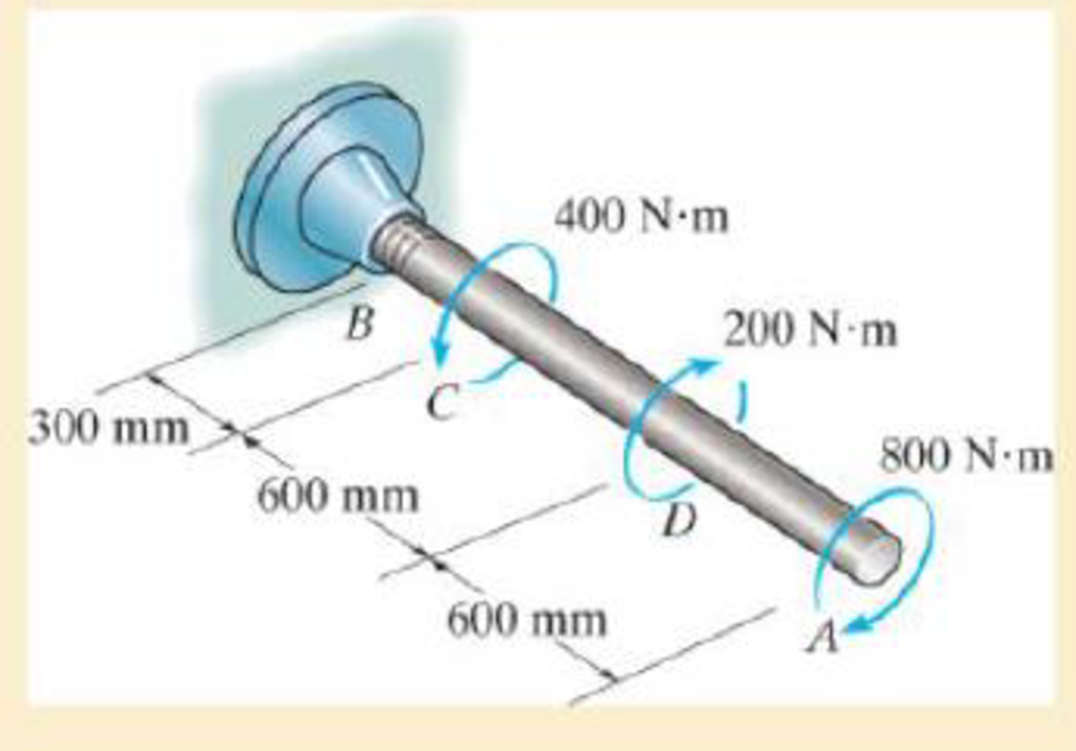
Chapter 5.4, Problem 53P
Determine the angle of twist of the end A.
Expert Solution & Answer
Want to see the full answer?
Check out a sample textbook solution
Students have asked these similar questions
180-
Dimensions in mm
100
100
D
E
Steel B
Brass
60 kN
40 kN
40-mm diam.
30-mm diam.
PROBLEM 2.40
Solve Prob. 2.39, assuming that rod AC is made of brass and
rod CE is made of steel.
PROBLEM 2.39 Two cylindrical rods, one of steel and the
other of brass, are joined at C and restrained by rigid supports at A
and E. For the loading shown and knowing that E = 200 GPa
and E, 105 GPa, determine (a) the reactions at A and E, (b) the
deflection of point C.
=
R = 45.5 kN ←
A
Dimensions in mm
100
100
-180-
-120-+-
C
D
Steel B
Brass
60 kN
40 kN
40-mm diam.
30-mm diam.
E
PROBLEM 2.39
Two cylindrical rods, one of steel and the other of brass, are joined at
Cand restrained by rigid supports at A and E. For the loading shown
and knowing that E = 200 GPa and E₁ = 105 GPa, determine
(a) the reactions at A and E, (b) the deflection of point C.
(read image) (Answer: vE = 0.514 m/s)
Chapter 5 Solutions
MECHANICS OF MATERIALS
Ch. 5.3 - The solid circular shaft is subjected to an...Ch. 5.3 - The hollow circular shaft is subjected to an...Ch. 5.3 - The shaft is hollow from A to B and solid from B...Ch. 5.3 - Determine the maximum shear stress in the...Ch. 5.3 - Determine the maximum shear stress in the shaft at...Ch. 5.3 - Determine the shear stress a: point A on the...Ch. 5.3 - The solid 50-mm-diameter shaft is subjected to the...Ch. 5.3 - The gear motor can develop 3 hp when it turns at...Ch. 5.3 - The solid shaft of radius r is subjected to a...Ch. 5.3 - The solid shaft of radius r is subjected to a...
Ch. 5.3 - Prob. 3PCh. 5.3 - The copper pipe has an outer diameter of 40 mm and...Ch. 5.3 - The copper pipe has an outer diameter of 2.50 in....Ch. 5.3 - The link acts as part of the elevator control for...Ch. 5.3 - The assembly consists of two sections of...Ch. 5.3 - A steel tube having an outer diameter of 2.5 in....Ch. 5.3 - The rod has a diameter of 1 in. and a weight of 10...Ch. 5.3 - The rod has a diameter of 1 in. and a weight of 15...Ch. 5.3 - Prob. 20PCh. 5.3 - The 60-mm-diameter solid shaft is subjected to the...Ch. 5.3 - The 60-mm-diameter solid shaft is subjected to the...Ch. 5.3 - The solid shaft is subjected to the distributed...Ch. 5.3 - If the tube is made from a material having an...Ch. 5.3 - Prob. 29PCh. 5.3 - The motor delivers 50 hp while turning at a...Ch. 5.3 - The solid steel shaft AC has a diameter of 25 mm...Ch. 5.3 - Prob. 35PCh. 5.4 - The 60 mm-diameter steel shaft is subjected to the...Ch. 5.4 - Prob. 10FPCh. 5.4 - The hollow 6061-T6 aluminum shaft has an outer and...Ch. 5.4 - A series of gears are mounted on the...Ch. 5.4 - The 80-mm-diameter shaft is made of steel. If it...Ch. 5.4 - The 80-mm-diameter shaft is made of steel. If it...Ch. 5.4 - The propellers of a ship are connected to an A-36...Ch. 5.4 - Show that the maximum shear strain in the shaft is...Ch. 5.4 - Determine the angle of twist of end B with respect...Ch. 5.4 - Determine the maximum allowable torque T. Also,...Ch. 5.4 - If the allowable shear stress is allow = 80 MPa,...Ch. 5.4 - Determine the angle of twist of the end A.Ch. 5.4 - The hydrofoil boat has an A992 steel propeller...Ch. 5.4 - Also, calculate the absolute maximum shear stress...Ch. 5.4 - If a torque of T = 50 N m is applied to the bolt...Ch. 5.4 - If a torque of T= 50N m is applied to the bolt...Ch. 5.4 - If the motor delivers 4 MW of power to the shaft...Ch. 5.4 - Determine the angle of twist at the free end A of...Ch. 5.5 - Gst = 75 GPa.Ch. 5.5 - The shaft is made of L2 tool steel, has a diameter...Ch. 5.5 - Each has a diameter of 25 mm and they are...Ch. 5.5 - Each has a diameter of 25 mm and they are...Ch. 5.5 - It is fixed at its ends and subjected to a torque...Ch. 5.5 - 5–89. Determine the absolute maximum shear stress...Ch. 5.7 - If the yield stress for brass is Y = 205 MPa,...Ch. 5.7 - By what percentage is the shaft of circular cross...Ch. 5.7 - Prob. 97PCh. 5.7 - Also, find the angle of twist of end B. The shaft...Ch. 5.7 - Also, find the corresponding angle of twist at end...Ch. 5.7 - Prob. 110PCh. 5.7 - Determine the average shear stress in the tube if...Ch. 5.7 - By what percentage is the torsional strength...Ch. 5.7 - Prob. 114PCh. 5.7 - Prob. 115PCh. 5.7 - Prob. 119PCh. 5.10 - Prob. 121PCh. 5.10 - If the radius of the fillet weld connecting the...Ch. 5.10 - Prob. 125PCh. 5.10 - Determine the radius of the elastic core produced...Ch. 5.10 - Prob. 128PCh. 5.10 - Determine the torque T needed to form an elastic...Ch. 5.10 - Determine the torque applied to the shaft.Ch. 5.10 - Prob. 131PCh. 5.10 - Determine the ratio of the plastic torque Tp to...Ch. 5.10 - Determine the applied torque T, which subjects the...Ch. 5.10 - Determine the radius of its elastic core if it is...Ch. 5.10 - Plot the shear-stress distribution acting along a...Ch. 5.10 - If the material obeys a shear stress-strain...Ch. 5.10 - It is made of an elastic perfectly plastic...Ch. 5.10 - Prob. 139PCh. 5.10 - Prob. 140PCh. 5.10 - Prob. 142PCh. 5.10 - Prob. 143PCh. 5 - The shaft is made of A992 steel and has an...Ch. 5 - The shaft is made of A992 steel and has an...Ch. 5 - Determine the shear stress at the mean radius p =...Ch. 5 - If the thickness of its 2014-T6-aluminum skin is...Ch. 5 - Determine which shaft geometry will resist the...Ch. 5 - If couple forces P = 3 kip are applied to the...Ch. 5 - If the allowable shear stress for the aluminum is...Ch. 5 - Determine the angle of twist of its end A if it is...Ch. 5 - This motion is caused by the unequal belt tensions...
Knowledge Booster


Learn more about
Need a deep-dive on the concept behind this application? Look no further. Learn more about this topic, mechanical-engineering and related others by exploring similar questions and additional content below.Similar questions
- 0.36 m Problem 2.27 P=5kN D Each of the links AB and CD is made of aluminum (E=75 GPa) and has a cross-sectional area of 125 mm². Knowing that they support the rigid member BC, determine the deflection of point E. B E 0.44 m 0.20 marrow_forward(read image) (Answer Given)arrow_forward(read image) Answer: A = 1192 Narrow_forward
- The correct answer is ~168 MPa, how was this found?arrow_forwardAir enters the compressor of a regenerative gas turbine engine at 310 K and 100 kPa, where it is compressed to 900 kPa and 650 K. The regenerator has an effectiveness of 75%, and the air enters the turbine at 1400 K. Assume variable specific heats for air. For a turbine efficiency of 90 percent, determine the amount of heat transfer in the regenerator. The amount of heat transfer in the regenerator is kJ/kg.arrow_forwardAir enters the compressor of a regenerative gas turbine engine at 310 K and 100 kPa, where it is compressed to 900 kPa and 650 K. The regenerator has an effectiveness of 79 percent, and the air enters the turbine at 1400 K. Assume constant specific heats for air at room temperature. The properties of air at room temperature are cp = 1.005 kJ/kg·K and k = 1.4. For a turbine efficiency of 90 percent, determine the amount of heat transfer in the regenerator. The amount of heat transfer in the regenerator is kJ/kg.arrow_forward
- Hints: Find the closed loop transfer function and then plot the step response for diFerentvalues of K in MATLAB. Show step response plot for different values of K. Auto Controls Show solutions and provide matlab code NO COPIED ANSWERS OR WILL REPORT!!!! Use own solutionarrow_forwardwhat is shear stress and normal? how to tell them while calculating?arrow_forward12 mm 45 mm 20 kN 20 kN 12 mm 45 mm PROBLEM 1.61 For the assembly and loading of Problem 1.60, determine (a) the average shearing stress in the pin at C, (b) the average bearing stress at C in member BC, (c) the average bearing stress at B in member BC. PROBLEM 1.60 Two horizontal 20-kN forces are applied to pin B of the assembly shown. Knowing that a pin of 20-mm diameter is used at each connection, determine the maximum value of the average normal stress (a) in link AB, (b) in link BC.arrow_forward
arrow_back_ios
SEE MORE QUESTIONS
arrow_forward_ios
Recommended textbooks for you
 International Edition---engineering Mechanics: St...Mechanical EngineeringISBN:9781305501607Author:Andrew Pytel And Jaan KiusalaasPublisher:CENGAGE L
International Edition---engineering Mechanics: St...
Mechanical Engineering
ISBN:9781305501607
Author:Andrew Pytel And Jaan Kiusalaas
Publisher:CENGAGE L
Understanding Torsion; Author: The Efficient Engineer;https://www.youtube.com/watch?v=1YTKedLQOa0;License: Standard YouTube License, CC-BY