
Concept explainers
Videos
The cross section of a concrete dam is as shown. For a 1-ft-wide dam section, determine (a) the resultant of the reaction forces exerted by the ground on the base AB of the dam, (b) the point of application of the resultant of part a, (c) the resultant of the pressure forces exerted by the water on the face BC of the dam.
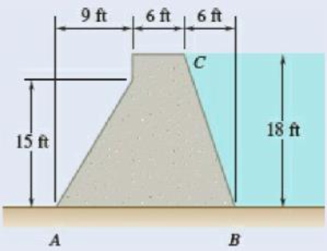
Fig. P5.80
(a)
The reaction force exerted by the ground on the base of the concrete dam.
Answer to Problem 5.80P
The resultant reaction forces acts on the base of the dam is
Explanation of Solution
Given that the width of the dam section
The free-body diagram consists of a
The wide length of the top section of dam is represented as
Write the equation for weight force of the dam.
Here, the weight of the dam is
Replace
Here, the width of the dam section is
Write the equation for the weight of the dam represented by the weights of its components.
Here, the weight of the dam by the components of fist section is
Substitute
Write the equation for the weight of the dam represented in the triangular section.
Here, the weight of the dam by the components of second section is
Substitute
Write the equation for the weight of the dam represented by the weights of its components.
Here, the weight of the dam by the components of third section is
Substitute
Write the equation for the weight of the dam represented by the weights of its components.
Here, the weight of the dam by the components of fourth section is
Substitute
Write the equation of the force pressure exerted by the ground on the base of the dam.
Here, the reaction force exerted on the dam is
Replace
Write the equilibrium equation for the section of dam acts along x axis (Refer Fig 1).
Here, the reaction force exerted by the ground on the base
Write the equilibrium equation for the section of beam acts along y axis and then calculate the reaction force (Refer Fig 1).
Here, the reaction force exerted by the ground on the base
Conclusion:
Substitute
Substitute
Substitute
Convert the above reaction force value into kips.
Therefore, the resultant reaction forces acts on the base of the dam is
(b)
The point of forces acts on the base
Answer to Problem 5.80P
The point in which the forces acts on the base
Explanation of Solution
The distance from the base of the dam to the point
The distance from the base of the dam to the mid part is.
The distance from the base of the dam to the point
The distance from the base of the dam to the total path is.
Write the equilibrium equation for the section on the base
Here, the different section of the dam is represented as
Conclusion:
Substitute
Solve the above equation for
Therefore, the point in which the forces acts on the base
(c)
The resultant pressure force exerted by the water on the face
Answer to Problem 5.80P
The resultant pressure force exerted by the water on the face
Explanation of Solution
The free body diagram of the water section
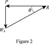
Write the equilibrium equation for the s resultant pressure force exerted by the water on the face
Here, the resultant pressure force exerted by the water on the dam is
Solve for the angle of resultant force exerted by the water on the dam by using trigonometric relation (Refer fig 2).
Conclusion:
Substitute
Substitute
Therefore, the resultant pressure force exerted by the water on the face
Want to see more full solutions like this?
Chapter 5 Solutions
VECTOR MECH...,STAT.+DYN.(LL)-W/ACCESS


- Correct answer is written below. Detailed and complete solution only. I will upvote, thank you.arrow_forwardCorrect answer is written below. Detailed and complete solution only. I will upvote, thank you.arrow_forwardCorrect answer is written below. Detailed and complete solution only. I will upvote, thank you.arrow_forward
- The single degree of freedom (SDOF) system that you studied under free vibration in Assignment #3 - Laboratory Component has been subjected to a strong ground motion. The acceleration at the base (excitation) and the acceleration at the roof (response) of the SDOF system was recorded with sampling rate 50 Hz (50 samples per second, or dt= 0.02 seconds). The file ElCentro.txt includes the two columns of acceleration data. The first column lists the acceleration at the base of the SDOF system. The second column lists the acceleration at the roof of the SDOF system. (a) Plot the time histories of the recorded accelerations at the base and at the roof of the SDOF system. (b) Compute the acceleration, velocity and displacement time histories of the roof of the SDOF system subjected to the recorded base acceleration using the Central Difference method. Plot the accel- eration, velocity and displacement time histories. Plot the restoring force, the damping force, and the inertia force time…arrow_forwardThe single degree of freedom (SDOF) system that you studied under free vibration in Assignment #3 - Laboratory Component has been subjected to a strong ground motion. The acceleration at the base (excitation) and the acceleration at the roof (response) of the SDOF system was recorded with sampling rate 50 Hz (50 samples per second, or dt= 0.02 seconds). The file ElCentro.txt includes the two columns of acceleration data. The first column lists the acceleration at the base of the SDOF system. The second column lists the acceleration at the roof of the SDOF system. (a) Plot the time histories of the recorded accelerations at the base and at the roof of the SDOF system. (b) Compute the acceleration, velocity and displacement time histories of the roof of the SDOF system subjected to the recorded base acceleration using the Central Difference method. Plot the accel- eration, velocity and displacement time histories. Plot the restoring force, the damping force, and the inertia force time…arrow_forwardA tensile specimen made of hot-rolled AISI 1020 steel is loaded to point corresponding to a strain of 43%. 60 Su = 66 ksi Stress σ (ksi) 40 B 20 0 0 0 T H Sy = 39 ksi Se = 36 ksi Hot-rolled 1020 steel F 10 20 30 40 50 60 70 80 90 100 110 120 130 140 150 160 Strain € (%) T 1.1 1.2 1.3 1.4 1.5 1.6 1.7 1.8 1.9 2.0 2.1 2.2 2.3 2.4 2.5 2.6 Area ratio R 0.1 0.2 0.3 0.4 0.5 Area reduction A, What value of strain is applicable to this location? 0.6arrow_forward
- A tensile specimen made of hot-rolled AISI 1020 steel is loaded to point corresponding to a strain of 40%. 60 Su = 66 ksi Stress σ (ksi) S₁ = 39 ksi 40 Se = 36 ksi Hot-rolled 1020 steel 20 0 10 20 30 40 50 60 70 80 90 100 110 120 130 140 150 160 Strain € (%) 0 1.1 1.2 1.3 1.4 1.5 1.6 1.7 1.8 1.9 2.0 2.1 2.2 2.3 2.4 2.5 2.6 Area ratio R 0.1 0.2 0.3 0.4 0.5 Area reduction A, What value of area ratio is applicable to this location? 0.6arrow_forwardA tensile specimen made of hot-rolled AISI 1020 steel is loaded to point corresponding to a strain of 43%. 60 Su = 66 ksi Stress σ (ksi) 20 Sy = 39 ksi Se = 36 ksi Hot-rolled 1020 steel F 0 10 20 30 40 50 60 70 80 90 100 110 120 130 140 150 160 Strain € (%) 0 1.1 1.2 1.3 1.4 1.5 1.6 1.7 1.8 1.9 2.0 2.1 2.2 2.3 2.4 2.5 2.6 Area ratio R 0.1 0.2 0.3 0.4 0.5 Area reduction A, What value of area reduction is applicable to this location? 0.6arrow_forwardTable of Measurements and Results: Reading m/s Ji- a (wh Nu h Re Nu Error% (C) (°C) 2 1 Discussion: 1-Estimate the heat transfer and experimental value of the heat transfer coefficient hex with its unit and Nusselt number Nu expl 2- Find the percentage error for the value of the experimental Nusselt number. 3-Draw the graph showing a relationship between the temperatures difference (T-T) and theoretical and experimental value of Nusselt number. 4-The forced convection heat transfer coefficient of a plate depends on which of the following: a-gravity. b-velocity of fluid. e-conductivity of fluid. d-conductivity of plate material. Experiment: Internal Forced convenction Heat trovate on now through t objectives. Study the convection heat transfer of air flow through stage Calculations. Q & (T-T) Vary Re Q. heup A (TT) (T. Te-T ASPL Nep Re 117 RITT 14 ' 14arrow_forward
- If AE = 1.6 m, ED = CD = 1.9 m and F = 3.1 kN, then find the magnitude of the force acting in EB. B 30° 30° C E D ED m DC m ♥F KNarrow_forwardAssume multiple single degree of freedom systems with natural periods T ∈ [0.05, 2.00] seconds with in- crement of period dT = 0.05 seconds. Assume three cases of damping ratio: Case (A) ξ = 0%; Case (B) ξ = 2%; Case (C) ξ = 5%. The systems are initially at rest. Thus, the initial conditions are u(t = 0) = 0 and ̇u(t = 0) = 0. The systems are subjected to the base acceleration that was provided in the ElCentro.txt file (i.e., first column). For the systems in Case (A), Case (B), and Case (C) and for each natural period compute the peak acceleration, peak velocity, and peak displacement responses to the given base excitation. Please, use the Newmark method for β = 1/4 (average acceleration) to compute the responses. Create three plots with three lines in each plot. The first plot will have the peak accelerations in y-axis and the natural period of the system in x-axis. The second plot will have the peak velocities in y-axis and the natural period of the system in x-axis. The third plot…arrow_forwardDetermine the resultant stress at points P and Q.arrow_forward
 Elements Of ElectromagneticsMechanical EngineeringISBN:9780190698614Author:Sadiku, Matthew N. O.Publisher:Oxford University Press
 Mechanics of Materials (10th Edition)Mechanical EngineeringISBN:9780134319650Author:Russell C. HibbelerPublisher:PEARSON
 Thermodynamics: An Engineering ApproachMechanical EngineeringISBN:9781259822674Author:Yunus A. Cengel Dr., Michael A. BolesPublisher:McGraw-Hill Education
 Control Systems EngineeringMechanical EngineeringISBN:9781118170519Author:Norman S. NisePublisher:WILEY
 Mechanics of Materials (MindTap Course List)Mechanical EngineeringISBN:9781337093347Author:Barry J. Goodno, James M. GerePublisher:Cengage Learning
 Engineering Mechanics: StaticsMechanical EngineeringISBN:9781118807330Author:James L. Meriam, L. G. Kraige, J. N. BoltonPublisher:WILEY