
Statics and Mechanics of Materials Plus Mastering Engineering with Pearson eText - Access Card Package (5th Edition)
5th Edition
ISBN: 9780134301006
Author: Russell C. Hibbeler
Publisher: PEARSON
expand_more
expand_more
format_list_bulleted
Concept explainers
Videos
Textbook Question
Chapter 5.3, Problem 13P
Determine the force in each member of the truss and state if the members are in tension or compression. Set P1 = 10 kN, P2 = 8 kN.
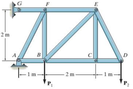
Probs. 5-13/14
Expert Solution & Answer
Want to see the full answer?
Check out a sample textbook solution
Students have asked these similar questions
Consider a double-fluid manometer attached to an air pipe shown below. If the specific gravity ofone fluid is 13.8, determine the specific gravity of the other fluid for the indicated absolutepressure of air. Take the atmospheric pressure to be 95 kPa
A race car enters the circular portion of a track that has a radius of 65 m. Disregard the 70 m in the picture. When the car enters the curve at point P, it is traveling with a speed of 120 km/h that is increasing at 5 m/s^2 . Three seconds later, determine the x and y components of velocity and acceleration of the car. I'm having trouble getting the correct y component of acceleration. all the other answers are correct. thank you!
Figure: 06_P041
Copyright 2013 Pearson Education, publishing a Prentice Hall
2. Determine the force that the jaws J of the metal cutters exert on the smooth cable C if 100-N
forces are applied to the handles. The jaws are pinned at E and A, and D and B. There is also
a pin at F.
400 mm
15°
20 mm
A
15°
15
D
B
30 mm² 80 mm
20 mm
400 mm
Figure: 06_P090
Copyright 2013 Pearson Education, publishing as Prentice Hall
15°
100 N
100 N
15°
Chapter 5 Solutions
Statics and Mechanics of Materials Plus Mastering Engineering with Pearson eText - Access Card Package (5th Edition)
Ch. 5.3 - In each ease, calculate the support reactions and...Ch. 5.3 - Identify the zero-force members in each truss....Ch. 5.3 - Determine the force in each member of the truss...Ch. 5.3 - Determine the force in each member of the truss...Ch. 5.3 - Determine the force in each member of the truss...Ch. 5.3 - Determine the greatest load P that can be applied...Ch. 5.3 - Identify the zero-force members in the truss....Ch. 5.3 - Determine the force in each member of the truss...Ch. 5.3 - Determine the force in each member of the truss...Ch. 5.3 - Determine the force in each member of the truss...
Ch. 5.3 - Determine the force in each member of the truss...Ch. 5.3 - Determine the force in each member of the truss...Ch. 5.3 - Determine the force in each member of the truss,...Ch. 5.3 - Determine the force in each member of the truss,...Ch. 5.3 - Determine the force in each member of the truss...Ch. 5.3 - Determine the force in each member of the truss in...Ch. 5.3 - Members AB and BC can each support a maximum...Ch. 5.3 - Members AB and BC can each support a maximum...Ch. 5.3 - Determine the force in each member of the truss...Ch. 5.3 - If the maximum force that any member can support...Ch. 5.3 - Determine the force in each member of the truss...Ch. 5.3 - Determine the force in each member of the truss...Ch. 5.3 - Determine the force in each member of the truss...Ch. 5.3 - Determine the force in each member of the truss...Ch. 5.4 - Determine the force in members BC, CF, and FE and...Ch. 5.4 - Determine the force in members LK, KC, and CD of...Ch. 5.4 - Determine the force in members KJ, KD, and CD of...Ch. 5.4 - Determine the force in members EF, CF, and BC of...Ch. 5.4 - Determine the force in members GF, GD, and CD of...Ch. 5.4 - Determine the force in members DC, HI, and JI of...Ch. 5.4 - Determine the force in members DC, HC and HI of...Ch. 5.4 - Determine the force in members ED, EH, and GH of...Ch. 5.4 - Determine the force in members HG, HE, and DE of...Ch. 5.4 - Determine the force in members CD, HI, and CH of...Ch. 5.4 - Determine the force in members CD, CJ, KJ, and DJ...Ch. 5.4 - Prob. 22PCh. 5.4 - The Howe truss is subjected to the loading shown....Ch. 5.4 - The Howe truss is subjected to the loading shown....Ch. 5.4 - Determine the force in members EF, CF, and BC, and...Ch. 5.4 - Determine the force in members AF, BF, and BC, and...Ch. 5.4 - Prob. 27PCh. 5.4 - Determine the force in members BC, BE, and EF of...Ch. 5.4 - Prob. 29PCh. 5.4 - Determine the force in members CD, CF, and CG and...Ch. 5.4 - Determine the force developed in members FE, EB,...Ch. 5.5 - In each ease, identify any two-force members, and...Ch. 5.5 - F5-13. Determine the force P needed to hold the...Ch. 5.5 - Determine the horizontal and vertical components...Ch. 5.5 - If a 100-N force is applied to the handles of the...Ch. 5.5 - Determine the horizontal and vertical components...Ch. 5.5 - Determine the force P required to hold the 100-lb...Ch. 5.5 - In each case, determine the force P required to...Ch. 5.5 - Determine the force P required to hold the 50-kg...Ch. 5.5 - Determine the force P required to hold the 150-kg...Ch. 5.5 - Determine the reactions at the supports A, C, and...Ch. 5.5 - Determine the resultant force at pins A, B, and C...Ch. 5.5 - Determine the reactions at the supports at A, E,...Ch. 5.5 - The wall crane supports a load of 700 lb....Ch. 5.5 - The wall crane supports a load of 700 lb....Ch. 5.5 - Determine the horizontal and vertical components...Ch. 5.5 - Determine the force in members FD and DB of the...Ch. 5.5 - Determine the force that the smooth 20-kg cylinder...Ch. 5.5 - The three power lines exert the forces shown on...Ch. 5.5 - The pumping unit is used to recover oil. When the...Ch. 5.5 - Determine the force that the jaws J of the metal...Ch. 5.5 - Prob. 47PCh. 5.5 - Prob. 48PCh. 5.5 - Prob. 49PCh. 5.5 - Determine the force created in the hydraulic...Ch. 5.5 - The hydraulic crane is used to lift the 1400-lb...Ch. 5.5 - Determine force P on the cable if the spring is...Ch. 5.5 - Prob. 53PCh. 5.5 - Prob. 54PCh. 5.5 - Prob. 55PCh. 5.5 - Determine the force P on the cable if the spring...Ch. 5.5 - Prob. 57PCh. 5.5 - Prob. 58PCh. 5.5 - Prob. 59PCh. 5.5 - Prob. 60PCh. 5.5 - The platform scale consists of a combination of...Ch. 5 - All the problems solutions must include FBDs....Ch. 5 - Determine the force in each member of the truss...Ch. 5 - Determine the force in member GJ and GC of the...Ch. 5 - Determine the force in members GF, FB, and BC of...Ch. 5 - Prob. 5RPCh. 5 - Determine the horizontal and vertical components...Ch. 5 - Prob. 7RPCh. 5 - Determine the resultant forces at pins B and C on...
Knowledge Booster


Learn more about
Need a deep-dive on the concept behind this application? Look no further. Learn more about this topic, mechanical-engineering and related others by exploring similar questions and additional content below.Similar questions
- A telemetry system is used to quantify kinematic values of a ski jumper immediately before the jumper leaves the ramp. According to the system r=560 ft , r˙=−105 ft/s , r¨=−10 ft/s2 , θ=25° , θ˙=0.07 rad/s , θ¨=0.06 rad/s2 Determine the velocity of the skier immediately before leaving the jump. The velocity of the skier immediately before leaving the jump along with its direction is ? I have 112.08 ft/s but can't seem to get the direction correct. Determine the acceleration of the skier at this instant. At this instant, the acceleration of the skier along with its direction is ? acceleration is 22.8 ft/s^2 but need help with direction. Need help with velocity direction and acceleration direction please.arrow_forwardFor Problems 18-22 (Table 7-27), design a V-belt drive. Specify the belt size, the sheave sizes, the number of belts, the actual output speed, and the center distance.arrow_forwardonly 21arrow_forward
- only 41arrow_forwardNormal and tangential components-relate to x-y coordinates A race car enters the circular portion of a track that has a radius of 65 m. When the car enters the curve at point P, it is traveling with a speed of 120 km/h that is increasing at 5 m/s^2 . Three seconds later, determine the x and y components of velocity and acceleration of the car. I need help with finding the y component of the total acceleration. I had put -32 but its incorrect. but i keep getting figures around that numberarrow_forwardThe bracket BCD is hinged at C and attached to a control cable at B. Let F₁ = 275 N and F2 = 275 N. F1 B a=0.18 m C A 0.4 m -0.4 m- 0.24 m Determine the reaction at C. The reaction at C N Z F2 Darrow_forward
- Consider the angle bar shown in the given figure A W 240 mm B 80 mm Draw the free-body diagram needed to determine the reactions at A and B when a = 150 mm. This problem could also be approached as a 3-force body using method of Section 4.2B.arrow_forwardA telemetry system is used to quantify kinematic values of a ski jumper immediately before the jumper leaves the ramp. According to the system r=560 ft , r˙=−105 ft/s , r¨=−10 ft/s2 , θ=25° , θ˙=0.07 rad/s , θ¨=0.06 rad/s2 Determine the velocity of the skier immediately before leaving the jump. The velocity of the skier immediately before leaving the jump along with its direction is ? I have 112.08 ft/s but can't seem to get the direction correct. Determine the acceleration of the skier at this instant. At this instant, the acceleration of the skier along with its direction is ? acceleration is 22.8 ft/s^2 but need help with direction. Need help with velocity direction and acceleration direction please.arrow_forwardFor the stop bracket shown, locate the x coordinate of the center of gravity. Consider a = = 16.50 mm. 34 mm 62 mm 51 mm 10 mm 100 mm 88 mm 55 mm 45 mm The x coordinate of the center of gravity is mm.arrow_forward
- In the given figure, the bent rod ABEF is supported by bearings at C and D and by wire AH. The portion AB of the rod is 250 mm long, and the load W is 580 N. Assume that the bearing at D does not exert any axial thrust. H B A с 30° 250 mm D Z 50 mm 300 mm F 250 mm 50 mm W Draw the free-body diagram needed to determine the tension in wire AH and the reactions at C and D.arrow_forwardA 10-ft boom is acted upon by the 810-lb force as shown in the figure. D 6 ft 6 ft E B 7 ft C 6 ft x 4 ft W Draw the free-body diagram needed to determine the tension in each cable and the reaction at the ball-and-socket joint at A.arrow_forwardLocate the center of gravity of the sheet-metal form shown. Given: r = 26.40 mm . 50 mm 40 mm X 150 mm The center of gravity (✗) of the sheet-metal form is The center of gravity (Y) of the sheet-metal form is The center of gravity ( Z ) of the sheet-metal form is mm. mm. (Round the final answer to three decimal places.) mm.arrow_forward
arrow_back_ios
SEE MORE QUESTIONS
arrow_forward_ios
Recommended textbooks for you
 Elements Of ElectromagneticsMechanical EngineeringISBN:9780190698614Author:Sadiku, Matthew N. O.Publisher:Oxford University Press
 Mechanics of Materials (10th Edition)Mechanical EngineeringISBN:9780134319650Author:Russell C. HibbelerPublisher:PEARSON
 Thermodynamics: An Engineering ApproachMechanical EngineeringISBN:9781259822674Author:Yunus A. Cengel Dr., Michael A. BolesPublisher:McGraw-Hill Education
 Control Systems EngineeringMechanical EngineeringISBN:9781118170519Author:Norman S. NisePublisher:WILEY
 Mechanics of Materials (MindTap Course List)Mechanical EngineeringISBN:9781337093347Author:Barry J. Goodno, James M. GerePublisher:Cengage Learning
 Engineering Mechanics: StaticsMechanical EngineeringISBN:9781118807330Author:James L. Meriam, L. G. Kraige, J. N. BoltonPublisher:WILEY
Elements Of Electromagnetics
Mechanical Engineering
ISBN:9780190698614
Author:Sadiku, Matthew N. O.
Publisher:Oxford University Press
Mechanics of Materials (10th Edition)
Mechanical Engineering
ISBN:9780134319650
Author:Russell C. Hibbeler
Publisher:PEARSON
Thermodynamics: An Engineering Approach
Mechanical Engineering
ISBN:9781259822674
Author:Yunus A. Cengel Dr., Michael A. Boles
Publisher:McGraw-Hill Education
Control Systems Engineering
Mechanical Engineering
ISBN:9781118170519
Author:Norman S. Nise
Publisher:WILEY
Mechanics of Materials (MindTap Course List)
Mechanical Engineering
ISBN:9781337093347
Author:Barry J. Goodno, James M. Gere
Publisher:Cengage Learning
Engineering Mechanics: Statics
Mechanical Engineering
ISBN:9781118807330
Author:James L. Meriam, L. G. Kraige, J. N. Bolton
Publisher:WILEY
Engineering Basics - Statics & Forces in Equilibrium; Author: Solid Solutions - Professional Design Solutions;https://www.youtube.com/watch?v=dQBvQ2hJZFg;License: Standard YouTube License, CC-BY