
VECTOR MECHANICS FOR ENGINEERS: STATICS
12th Edition
ISBN: 9781259977121
Author: BEER
Publisher: MCG
expand_more
expand_more
format_list_bulleted
Concept explainers
Videos
Textbook Question
Chapter 5.2, Problem 5.63P
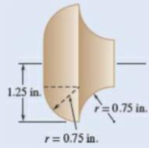
Determine the total surface area of the solid brass knob shown.
Fig. P5.62 and P5.63
Expert Solution & Answer
Want to see the full answer?
Check out a sample textbook solution
Students have asked these similar questions
Where on the beam below is the Maximum Deflection likely to occur?
2P
A
"ती
Point A
Point B
Point C
Point D
Point B or Point D
८
B
प
Sign in
||!
PDE 321 proje X
IMB321
PDF Lecture 5 X PDF Planet Ec X
PDF
Planet Ec X
PDF PEABWX
PDF meeting x
PDF
GSS Quo X
PDF
File C:/Users/KHULEKANI/Downloads/CIVE%20281%20Ass-2.pdf
Draw
| | All | a | Ask Copilot
+
1
of 7
| D
SOLUTION
B
PROBLEM 12.16
Block 4 has a mass of 40 kg, and block B has a mass of 8 kg. The
coefficients of friction between all surfaces of contact are μ, = 0.20
H = 0.15. Knowing that P = 50 N→, determine (a) the acceleration of
block B, (b) the tension in the cord.
Constraint of cable: 2x + (x-x1) = x + x = constant.
a+ag = 0,
or
aB = -a
Assume that block A moves down and block B moves up.
Block B: +/ΣF, = 0: NAB - WB cos 0 = 0
=ma: -T+μN + Wsin
=
We as
g
+ ΣΕ
We
Eliminate NAB and
aB-
NAB
B
Nas
HN
UNA
A
NA
-T+W(sin+μcоsе) = WB-
g
VD"M-
g
Block A: +/ΣF, = 0: NA-NAB - W₁cos + Psinė = 0
N₁ = N AB+W cose - Psin
=
(WB+WA)cose - Psinė
ΣF=ma -T+Wsino-FAB-F + Pcos =
CIVE 281 X
+
Ждал
g
Q |
го
||
حالم
☑
Where on the below beam is the Maxiumum Slope likely to occur?
120
Point A
Point B
Point C
Point B or Point C
B
с
Chapter 5 Solutions
VECTOR MECHANICS FOR ENGINEERS: STATICS
Ch. 5.1 - 5.1 through 5.9 Locate the centroid of the plane...Ch. 5.1 - Locate the centroid of the plane area shown.Ch. 5.1 - Locate the centroid of the plane area shown.Ch. 5.1 - Locate the centroid of the plane area shown.Ch. 5.1 - Locate the centroid of the plane area shown.Ch. 5.1 - Locate the centroid of the plane area shown.Ch. 5.1 - Locate the centroid of the plane area shown.Ch. 5.1 - Locate the centroid of the plane area shown.Ch. 5.1 - Locate the centroid of the plane area shown.Ch. 5.1 - Locate the centroid of the plane area shown.
Ch. 5.1 - Locate the centroid of the plane area shown.Ch. 5.1 - Locate the centroid of the plane area shown.Ch. 5.1 - Locate the centroid of the plane area shown.Ch. 5.1 - Locate the centroid of the plane area shown.Ch. 5.1 - Locate the centroid of the plane area shown.Ch. 5.1 - PROBLEM 5.16 Determine the y coordinate of the...Ch. 5.1 - Show that as r1 approaches r2, the location of the...Ch. 5.1 - For the area shown, determine the ratio a/b for...Ch. 5.1 - For the semiannular area of Prob. 5.12, determine...Ch. 5.1 - A built-up beam is constructed by nailing seven...Ch. 5.1 - The horizontal x axis is drawn through the...Ch. 5.1 - The horizontal x-axis is drawn through the...Ch. 5.1 - PROBLEM 5.23 The first moment of the shaded area...Ch. 5.1 - A thin, homogeneous wire is bent to form the...Ch. 5.1 - A thin, homogeneous wire is bent to form the...Ch. 5.1 - A thin, homogeneous wire is bent to form the...Ch. 5.1 - A thin, homogeneous wire is bent to form the...Ch. 5.1 - The homogeneous wire ABC is bent into a...Ch. 5.1 - The frame for a sign is fabricated from thin, flat...Ch. 5.1 - The homogeneous wire ABCD is bent as shown and is...Ch. 5.1 - The homogeneous wire ABCD is bent as shown and is...Ch. 5.1 - Determine the distance h for which the centroid of...Ch. 5.1 - Knowing that the distance h has been selected to...Ch. 5.2 - Determine by direct integration the centroid of...Ch. 5.2 - 5.34 through 5.36 Determine by direct integration...Ch. 5.2 - 5.34 through 5.36 Determine by direct integration...Ch. 5.2 - 5.37 through 5.39 Determine by direct integration...Ch. 5.2 - 5.37 through 5.39 Determine by direct integration...Ch. 5.2 - 5.37 through 5.39 Determine by direct integration...Ch. 5.2 - 5.40 and 5.41 Determine by direct integration the...Ch. 5.2 - 5.40 and 5.41 Determine by direct integration the...Ch. 5.2 - Determine by direct integration the centroid of...Ch. 5.2 - 5.43 and 5.44 Determine by direct integration the...Ch. 5.2 - 5.43 and 5.44 Determine by direct integration the...Ch. 5.2 - 5.45 and 5.46 A homogeneous wire is bent into the...Ch. 5.2 - 5.45 and 5.46 A homogeneous wire is bent into the...Ch. 5.2 - A homogeneous wire is bent into the shape shown....Ch. 5.2 - 5.48 and 5.49 Determine by direct integration the...Ch. 5.2 - 5.48 and 5.49 Determine by direct integration the...Ch. 5.2 - Determine the centroid of the area shown in terms...Ch. 5.2 - Determine the centroid of the area shown when a =...Ch. 5.2 - Determine the volume and the surface area of the...Ch. 5.2 - Determine the volume and the surface area of the...Ch. 5.2 - Determine the volume and the surface area of the...Ch. 5.2 - Determine the volume and the surface area of the...Ch. 5.2 - Determine the volume of the solid generated by...Ch. 5.2 - Verify that the expressions for the volumes of the...Ch. 5.2 - Knowing that two equal caps have been removed from...Ch. 5.2 - Three different drive belt profiles are to be...Ch. 5.2 - Determine the capacity, in liters, of the punch...Ch. 5.2 - Determine the volume and total surface area of the...Ch. 5.2 - Determine the volume and weight of the solid brass...Ch. 5.2 - Determine the total surface area of the solid...Ch. 5.2 - Determine the volume of the brass collar obtained...Ch. 5.2 - The shade for a wall-mounted light is formed from...Ch. 5.3 - 5.66 and 5.67 For the beam and loading shown,...Ch. 5.3 - 5.66 and 5.67 For the beam and loading shown,...Ch. 5.3 - 5.68 through 5.73 Determine the reactions at the...Ch. 5.3 - 5.68 through Determine the reactions at the beam...Ch. 5.3 - 5.68 through 5.73 Determine the reactions at the...Ch. 5.3 - 5.68 through Determine the reactions at the beam...Ch. 5.3 - 5.68 through 5.73 Determine the reactions at the...Ch. 5.3 - 5.68 through 5.73 Determine the reactions at the...Ch. 5.3 - Determine (a) the distance a so that the vertical...Ch. 5.3 - Determine (a) the distance a so that the reaction...Ch. 5.3 - Determine the reactions at the beam supports for...Ch. 5.3 - Determine (a) the distributed load w0 at the end D...Ch. 5.3 - The beam AB supports two concentrated loads and...Ch. 5.3 - For the beam and loading of Prob. 5.78, determine...Ch. 5.3 - The cross section of a concrete dam is as shown....Ch. 5.3 - The cross section of a concrete dam is as shown....Ch. 5.3 - The dam for a lake is designed to withstand the...Ch. 5.3 - The base of a dam for a lake is designed to resist...Ch. 5.3 - Prob. 5.84PCh. 5.3 - Prob. 5.85PCh. 5.3 - The 3 4-m side AB of a tank is hinged at its...Ch. 5.3 - The 3 4-m side of an open tank is hinged at its...Ch. 5.3 - A 0.5 0.8-m gate AB is located at the bottom of a...Ch. 5.3 - A 0.5 0.8-m gate AB is located at the bottom of a...Ch. 5.3 - A 4 2-ft gate is hinged at A and is held in...Ch. 5.3 - Fig. P5.90 5.91 Solve Prob. 5.90 if the gate...Ch. 5.3 - A prismatically shaped gate placed at the end of a...Ch. 5.3 - A prismatically shaped gate placed at the end of a...Ch. 5.3 - A long trough is supported by a continuous hinge...Ch. 5.3 - The square gate AB is held in the position shown...Ch. 5.4 - Consider the composite body shown. Determine (a)...Ch. 5.4 - A cone and a cylinder of the same radius a and...Ch. 5.4 - Determine the location of the center of gravity of...Ch. 5.4 - Prob. 5.99PCh. 5.4 - For the stop bracket shown, locate the x...Ch. 5.4 - Fig. P5.100 and P5.101 5.101 For the stop bracket...Ch. 5.4 - Prob. 5.102PCh. 5.4 - Prob. 5.103PCh. 5.4 - For the machine element shown, locate the y...Ch. 5.4 - For the machine element shown, locate the x...Ch. 5.4 - 5.106 and 5.107 Locate the center of gravity of...Ch. 5.4 - 5.106 and 5.107 Locate the center of gravity of...Ch. 5.4 - A corner reflector for tracking by radar has two...Ch. 5.4 - A wastebasket, designed to fit in the corner of a...Ch. 5.4 - An elbow for the duct of a ventilating system is...Ch. 5.4 - A window awning is fabricated from sheet metal...Ch. 5.4 - Locate the center of gravity of the sheet-metal...Ch. 5.4 - Locate the center of gravity of the sheet-metal...Ch. 5.4 - A thin steel wire with a uniform cross section is...Ch. 5.4 - The frame of a greenhouse is constructed from...Ch. 5.4 - Locate the center of gravity of the figure shown,...Ch. 5.4 - Prob. 5.117PCh. 5.4 - A scratch awl has a plastic handle and a steel...Ch. 5.4 - PROBLEM 5.117 A bronze bushing is mounted inside a...Ch. 5.4 - PROBLEM 5.120 A brass collar, of length 2.5 in.,...Ch. 5.4 - PROBLEM 5.121 The three legs of a small...Ch. 5.4 - Prob. 5.122PCh. 5.4 - Determine by direct integration the values of x...Ch. 5.4 - Prob. 5.124PCh. 5.4 - PROBLEM 5.125 Locate the centroid of the volume...Ch. 5.4 - Prob. 5.126PCh. 5.4 - Prob. 5.127PCh. 5.4 - PROBLEM 5.128 Locate the centroid of the volume...Ch. 5.4 - PROBLEM 5.129 Locate the centroid of the volume...Ch. 5.4 - Show that for a regular pyramid of height h and n...Ch. 5.4 - PROBLEM 5.131 Determine by direct integration the...Ch. 5.4 - PROBLEM 5.132 The sides and the base of a punch...Ch. 5.4 - Locate the centroid of the section shown, which...Ch. 5.4 - Locate the centroid of the section shown, which...Ch. 5.4 - Determine by direct integration the location of...Ch. 5.4 - Alter grading a lot, a builder places four stakes...Ch. 5 - 5.137 and 5.138 Locate the centroid of the plane...Ch. 5 - 5.137 and 5.138 Locate the centroid of the plane...Ch. 5 - Prob. 5.139RPCh. 5 - Determine by direct integration the centroid of...Ch. 5 - Determine by direct integration the centroid of...Ch. 5 - The escutcheon (a decorative plate placed on a...Ch. 5 - Determine the reactions at the supports for the...Ch. 5 - A beam is subjected to a linearly distributed...Ch. 5 - A tank is divided into two sections by a 1 1-m...Ch. 5 - Determine the y coordinate of the centroid of the...Ch. 5 - An 8-in.-diameter cylindrical duct and a 4 8-in....Ch. 5 - Three brass plates are brazed to a steel pipe to...
Knowledge Booster


Learn more about
Need a deep-dive on the concept behind this application? Look no further. Learn more about this topic, mechanical-engineering and related others by exploring similar questions and additional content below.Similar questions
- A very thin metallic sheet is placed between two wood plates of different thicknesses. Theplates are firmly pressed together and electricity is passed through the sheet. The exposed surfaces ofthe two plates lose heat to the ambient fluid by convection. Assume uniform heating at the interface.Neglect end effects and assume steady state.[a] Will the heat transfer through the two plates be the same? Explain.[b] Will the exposed surfaces be at the same temperature? Explainarrow_forwardDesign consideration requires that the surface of a small electronic package be maintained at atemperature not to exceed 82 o C. Noise constraints rule out the use of fans. The power dissipated inthe package is 35 watts and the surface area is 520 cm2 . The ambient temperature and surroundingwalls are assumed to be at 24 o C. The heat transfer coefficient is estimated to be 9.2 W/m2- oC andsurface emissivity is 0.7. Will the package dissipate the required power without violating designconstraints?arrow_forwardConsider radiation from a small surface at 100 oC which is enclosed by a much larger surface at24 o C. Determine the percent increase in the radiation heat transfer if the temperature of the smallsurface is doubled.arrow_forward
- A small electronic package with a surface area of 820 cm2 is placed in a room where the airtemperature is 28 o C. The heat transfer coefficient is 7.3 W/m2 - o C. You are asked to determine if it isjustified to neglect heat loss from the package by radiation. Assume a uniform surface temperature of78 o C and surface emissivity of 0.65 Assume further that room’s walls and ceiling are at a uniformtemperature of 16 o C.arrow_forwardA hollow metal sphere of outer radius or = 2 cm is heated internally with a variable output electricheater. The sphere loses heat from its surface by convection and radiation. The heat transfercoefficient is 22 W/ m2 - o C and surface emissivity is 0.92. The ambient fluid temperature is 20 o C andthe surroundings temperature is 14 oC. Construct a graph of the surface temperature corresponding toheating rates ranging from zero to 100 watts. Assume steady state. Use a simplified model forradiation exchange based on a small gray surface enclosed by a much larger surface at 14 o C.arrow_forward2. A program to make the part depicted in Figure 26.A has been created, presented in figure 26.B, but some information still needs to be filled in. Compute the tool locations, depths, and other missing information to present a completed program. (Hint: You may have to look up geometry for the center drill and standard 0.5000 in twist drill to know the required depth to drill). Dashed line indicates - corner of original stock Intended toolpath-tangent - arc entry and exit sized to programmer's judgment 026022 (Slot and Drill Part) (Setup Instructions. (UNITS: Inches (WORKPIECE MAT'L: SAE 1020 STEEL (Workpiece: 3.25 x 2.00 x0.75 in. Plate (PRZ Location G54: ( XY 0.0 Upper Left of Fixture ( TOP OF PART 2-0 (Tool List: ) ( T04 T02 0.500 IN 4 FLUTE FLAT END MILL) #4 CENTER DRILL ' T02 0.500 TWIST DRILL N010 GOO G90 G17 G20 G49 G40 G80 G54 N020 M06 T02 (0.5 IN 4-FLUTE END MILL) R0.750 N030 S760 M03 G00 x N040 043 H02 2 Y (P1) (RAPID DOWN -TLO) P4 NO50 MOB (COOLANT ON) N060 G01 X R1.000 N070…arrow_forward
- 6–95. The reaction of the ballast on the railway tie can be assumed uniformly distributed over its length as shown. If the wood has an allowable bending stress of σallow=1.5 ksi, determine the required minimum thickness t of the rectangular cross section of the tie to the nearest 18 in. Please include all steps. Also if you can, please explain how you found Mmax using an equation rather than using just the moment diagram. Thank you!arrow_forward6–53. If the moment acting on the cross section is M=600 N⋅m, determine the resultant force the bending stress produces on the top board. Please explain each step. Please explain how you got the numbers and where you plugged them in to solve the problem. Thank you!arrow_forwardSolving coplanar forcesarrow_forward
- Complete the following problems. Show your work/calculations, save as.pdf and upload to the assignment in Blackboard. 1. What are the x and y dimensions for the center position of holes 1,2, and 3 in the part shown in Figure 26.2 (below)? 6.0000 7118 Zero reference point 1.0005 1.0000 1.252 Bore C' bore 1.250 6.0000 .7118 0.2180 deep (3 holes) 2.6563 1.9445 3.000 diam. slot 0.3000 deep. 0.3000 wide 2.6563 1.9445arrow_forwardComplete the following problems. Show your work/calculations, save as.pdf and upload to the assignment in Blackboard. missing information to present a completed program. (Hint: You may have to look up geometry for the center drill and standard 0.5000 in twist drill to know the required depth to drill). 1. What are the x and y dimensions for the center position of holes 1,2, and 3 in the part shown in Figure 26.2 (below)? 6.0000 Zero reference point 7118 1.0005 1.0000 1.252 Bore 6.0000 .7118 Cbore 0.2180 deep (3 holes) 2.6563 1.9445 Figure 26.2 026022 (8lot and Drill Part) (Setup Instructions--- (UNITS: Inches (WORKPIECE NAT'L SAE 1020 STEEL (Workpiece: 3.25 x 2.00 x0.75 in. Plate (PRZ Location 054: ' XY 0.0 - Upper Left of Fixture TOP OF PART 2-0 (Tool List ( T02 0.500 IN 4 FLUTE FLAT END MILL #4 CENTER DRILL Dashed line indicates- corner of original stock ( T04 T02 3.000 diam. slot 0.3000 deep. 0.3000 wide Intended toolpath-tangent- arc entry and exit sized to programmer's judgment…arrow_forwardA program to make the part depicted in Figure 26.A has been created, presented in figure 26.B, but some information still needs to be filled in. Compute the tool locations, depths, and other missing information to present a completed program. (Hint: You may have to look up geometry for the center drill and standard 0.5000 in twist drill to know the required depth to drill).arrow_forward
arrow_back_ios
SEE MORE QUESTIONS
arrow_forward_ios
Recommended textbooks for you
 International Edition---engineering Mechanics: St...Mechanical EngineeringISBN:9781305501607Author:Andrew Pytel And Jaan KiusalaasPublisher:CENGAGE L
International Edition---engineering Mechanics: St...
Mechanical Engineering
ISBN:9781305501607
Author:Andrew Pytel And Jaan Kiusalaas
Publisher:CENGAGE L
Understanding Thermal Radiation; Author: The Efficient Engineer;https://www.youtube.com/watch?v=FDmYCI_xYlA;License: Standard youtube license