
Concept explainers
Videos
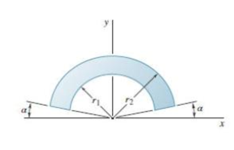
Show that as r1 approaches r2, the location of the centroid approaches that for an arc of circle of radius (r1 + r2)/2.
To show that as
Answer to Problem 5.17P
The location of the centroid for an arc of circle of radius
Explanation of Solution
Write the expression for the y-coordinate of the centroid of the sector with radius
Here
Write the expression for the area of the sector with radius
Write the expression for the y-coordinate of the centroid of the sector with radius
Here
Write the expression for the area of the sector with radius
Write the expression for
Substitute (I), (II), (III) and (IV) in the above equation to calculate
Write the expression for
Substitute (II) and (IV) in the above equation to calculate
Write the expression to calculate the y-coordinate of the centroid of the given area.
Substitute (V) and (VI) in the above equation to calculate
Write the expression for the y-coordinate of the centroid with an arc of radius
Rewrite the expression
Let
Substitute the above two expressions in (VIII) to rewrite.
Apply the limits
Rewrite r using
Conclusion:
Substitute (XII) in (VII) to calculate
Therefore, the above expression is same as that of the expression given in (VIII).
Thus, the location of the centroid for an arc of circle of radius
Want to see more full solutions like this?
Chapter 5 Solutions
VECTOR MECHANIC


- A steady-flow compressor is used to compress helium from 15 psia and 70°F at the inlet to 200 psia and 600°F at the outlet. The outlet area and velocity are 0.01 ft2 and 100 ft/s, respectively, and the inlet velocity is 53 ft/s. Determine the mass flow rate and the inlet area. The gas constant of helium is R = 2.6809 psia·ft3/lbm·R. The mass flow rate is lbm/s. The inlet area is ft2.arrow_forward1. The maximum and minimum stresses as well as the shear stress seen subjected the piece in plane A-A. Assume it is a cylinder with a diameter of 12.7mm 2. Draw the Mohr circle for the stress state using software. 3. Selection of the material for the prosthesis, which must be analyzed from the point of safety and cost view.arrow_forwardMarrow_forward
- × Your answer is incorrect. (Manometer) Determine the angle 0 of the inclined tube shown in figure below if the pressure at A is 1 psi greater than that at B. 1ft SG=0.61 十 A Ꮎ 1ft SG=1.0 8.8 ft 0 = Hi 15.20 deg Airarrow_forwardI don't know how to solve thisarrow_forward1. The maximum and minimum stresses as well as the shear stress seen subjected the piece in plane A-A. Assume it is a cylinder with a diameter of 12.7mm 2. Draw the Mohr circle for the stress state using software. 3. Selection of the material for the prosthesis, which must be analyzed from the point of safety and cost view.arrow_forward
- First, define the coordinate system XY with its origin at O2 and X-axis passing through O4 asshown above, then based on the provided steps Perform coordinate transformation from XY to xy to get the trajectory of point P. Show all the steps and calcualtionsarrow_forwardI don't know how to solve thisarrow_forwardQuestion 2 (40 Points) Consider the following double pendulum-like system with links ₁ and 12. The angles 0 and & could have angular velocities ėêk and êk, respectively, where ②k is a unit vector that points out of the page and is perpendicular to x and y. They could also have angular accelerations Ök and êk. The angle is defined relative to the angle 0. The link 12 is a spring and can extend or compress at a rate of 12. It can also have a rate of extension or compression Ï2. li y êr1 êe 12 χ 3 еф er2 ده لج 1) Express the velocity of the mass in terms of the unit vectors ê0, êr1, êø, and êr2, and any extension/contraction of the links (e.g.,. i; and Ï¿) (12 Points) 2) Express the acceleration of the mass in terms of the unit vectors ê¤, ê×1, êp, and êÃ2, and any extension/contraction of the links (e.g.,. İ; and Ï¿) (12 Points) 3) Express the velocity of the mass in terms of unit vectors î and ĵ that point in the x and y directions, respectively. Also include the appropriate,…arrow_forward
- provide step by step solutions for angles teta 3 and teta 4 by the vector loopmethod. Show work in: vector loop, vector equations, solution procedure.arrow_forward(Manometer) A tank is constructed of a series of cylinders having diameters of 0.35, 0.30, and 0.20 m as shown in the figure below. The tank contains oil, water, and glycerin and a mercury manometer is attached to the bottom as illustrated. Calculate the manometer reading, h. 0.11 m + SAE 30 Oil 0.13 m + Water 0.10 m Glycerin + 0.10 m Mercury h = marrow_forwardP = A piston having a cross-sectional area of 0.40 m² is located in a cylinder containing water as shown in the figure below. An open U-tube manometer is connected to the cylinder as shown. For h₁ = 83 mm and h = 111 mm what is the value of the applied force, P, acting on the piston? The weight of the piston is negligible. Hi 5597.97 N P Piston Water Mercuryarrow_forward
 International Edition---engineering Mechanics: St...Mechanical EngineeringISBN:9781305501607Author:Andrew Pytel And Jaan KiusalaasPublisher:CENGAGE L