| BIO Traction apparatus . In order to prevent muscle contraction from misaligning bones during healing (which can cause a permanent limp), injured or broken legs must be supported horizontally and at the same time kept under tension (traction) directed along the leg. One version of a device to accomplish this aim, the Russell traction apparatus, is shown in Figure 5.42 . This system allows the apparatus to support the full weight of the injured leg and at the same time provide the traction along the leg. If the leg to be supported weighs 47.0 N, (a) what must be the weight of Wand (b) what traction force does this system produce along the leg? Figure 5.42 Problem 8.
| BIO Traction apparatus . In order to prevent muscle contraction from misaligning bones during healing (which can cause a permanent limp), injured or broken legs must be supported horizontally and at the same time kept under tension (traction) directed along the leg. One version of a device to accomplish this aim, the Russell traction apparatus, is shown in Figure 5.42 . This system allows the apparatus to support the full weight of the injured leg and at the same time provide the traction along the leg. If the leg to be supported weighs 47.0 N, (a) what must be the weight of Wand (b) what traction force does this system produce along the leg? Figure 5.42 Problem 8.
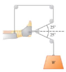
| BIO Traction apparatus. In order to prevent muscle contraction from misaligning bones during healing (which can cause a permanent limp), injured or broken legs must be supported horizontally and at the same time kept under tension (traction) directed along the leg. One version of a device to accomplish this aim, the Russell traction apparatus, is shown in Figure 5.42. This system allows the apparatus to support the full weight of the injured leg and at the same time provide the traction along the leg. If the leg to be supported weighs 47.0 N, (a) what must be the weight of Wand (b) what traction force does this system produce along the leg?
A planar double pendulum consists of two point masses \[m_1 = 1.00~\mathrm{kg}, \qquad m_2 = 1.00~\mathrm{kg}\]connected by massless, rigid rods of lengths \[L_1 = 1.00~\mathrm{m}, \qquad L_2 = 1.20~\mathrm{m}.\]The upper rod is hinged to a fixed pivot; gravity acts vertically downward with\[g = 9.81~\mathrm{m\,s^{-2}}.\]Define the generalized coordinates \(\theta_1,\theta_2\) as the angles each rod makes with thedownward vertical (positive anticlockwise, measured in radians unless stated otherwise).At \(t=0\) the system is released from rest with \[\theta_1(0)=120^{\circ}, \qquad\theta_2(0)=-10^{\circ}, \qquad\dot{\theta}_1(0)=\dot{\theta}_2(0)=0 .\]Using the exact nonlinear equations of motion (no small-angle or planar-pendulumapproximations) and assuming the rods never stretch or slip, determine the angle\(\theta_2\) at the instant\[t = 10.0~\mathrm{s}.\]Give the result in degrees, in the interval \((-180^{\circ},180^{\circ}]\).
What are the expected readings of the ammeter and voltmeter for the circuit in the figure below? (R = 5.60 Ω, ΔV = 6.30 V)
ammeter
I =
simple diagram to illustrate the setup for each law- coulombs law and biot savart law
Chapter 5 Solutions
Masteringphysics With Pearson Etext - Valuepack Access Card - For College Physics
Need a deep-dive on the concept behind this application? Look no further. Learn more about this topic, physics and related others by exploring similar questions and additional content below.


 Glencoe Physics: Principles and Problems, Student...PhysicsISBN:9780078807213Author:Paul W. ZitzewitzPublisher:Glencoe/McGraw-Hill
 College PhysicsPhysicsISBN:9781938168000Author:Paul Peter Urone, Roger HinrichsPublisher:OpenStax College
 Physics for Scientists and Engineers, Technology ...PhysicsISBN:9781305116399Author:Raymond A. Serway, John W. JewettPublisher:Cengage Learning
 Physics for Scientists and Engineers: Foundations...PhysicsISBN:9781133939146Author:Katz, Debora M.Publisher:Cengage Learning
 Physics for Scientists and Engineers with Modern ...PhysicsISBN:9781337553292Author:Raymond A. Serway, John W. JewettPublisher:Cengage Learning
 University Physics Volume 1PhysicsISBN:9781938168277Author:William Moebs, Samuel J. Ling, Jeff SannyPublisher:OpenStax - Rice University