Interpretation:
Considering the depth of material, the concentration profile should be determined. Also, the graph for the profile P for pre-deposition process should be plotted.
Concept introduction:
Constant source diffusion is the relationship of diffusion source with depth, diffusion coefficient and time. The relationship is given by using the below equation,
Where,
D is the diffusion coefficient.
t is the time.
x is the depth.
Constant source diffusion is of two types:
- Pre deposition step: It is the first step for constant source diffusion in which a small quantity of impurity is doped using the constant source.
- Drive in deposition: It is the second step for constant source diffusion in which the material is maintaining the higher value of temperature for a certain period of time.
Equation used for calculating the diffusion is,
Fick's Law of diffusion: This law states that molar flux is directly proportional to concentration gradient. The law is stated as:
Where,
J is the molar flux defined as the number of atoms passing per unit area per unit time.
D is the diffusion coefficient in
Factors affection diffusion are as follows:
- Temperature
- Diffusion coefficient
The following equation is stated as:
Where,
Q is the activation energy in calorie/ mole.
R is universal gas constant in
T is the absolute temperature in kelvin.
Explanation of Solution
Given Information:
The given equation for basis is:
Where,
c is the concentration considering pre deposition function.
D is the diffusion coefficient.
X is the depth.
T is the time.
erf is the error function.
The given boundary conditions are:
Depth =
Concentration of P at depth of
The temperature at which material is conducted is
Value of diffusion coefficient is
Total time for carrying out the process is
Equation considered for calculation is,
On integrating the above equation within limits,
Thus, the equation considered for calculation is,
Assuming the various values of depth required for calculation. Assumed values of depth are,
Calculation of concentration with respect to time and depth. Considering depth as
Value of diffusion coefficient (D) is
Total time for carrying out the process is
Substituting the given value in the above relation,
Using table for calculation of error function,
Thus, concentration at a depth of
Calculation of concentration with respect to time and depth. Considering depth as
Value of diffusion coefficient (D) is
Total time for carrying out the process is
Substituting the given value in the above relation,
When the value of error function exceeds the range of limit 4. The formula used for calculation of error function is,
Thus, concentration at a depth of
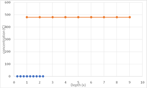
The table represents the data of concentration with variation in depth,
| Depth | Concentration |
Based on the given values drawing graph of concentration versus depth,

Thus, the required graph of concentration versus depth is shown above. As for pre deposition process concentration has dependency on time and depth, blue line is showing variation of concentration versus time and yellow line represents the variation of concentration with time.
Want to see more full solutions like this?
Chapter 5 Solutions
Essentials Of Materials Science And Engineering, Si Edition
- A 3-phase, 6-pole induction motor is con- nected to a 60 Hz supply. The voltage in- duced in the rotor bars is 4 V when the ro- tor is locked. If the motor turns in the same direction as the flux, calculate the approxi- mate voltage induced and its frequency: a. At 300 r/min b. At 1000 r/min c. At 1500 r/minarrow_forwardMake a drawing of the magnetic field cre- ated by a 3-phase, 12-pole induction motor. How can we change the direction of rota- tion of a 3-phase induction motor?arrow_forwardIn class, two approaches—Theorems 1 and 2 below—are discussed to prove asymptotic stability of asystem when ̇V = 0. Show the asymptotic stability of the system given in Eq. (1) by applying Theorem 1. Show the asymptotic stability of the system given in Eq. (1) by applying Theorem 2.arrow_forward
- Homework#5arrow_forwardDescribe the principle of operation of a lin- ear induction motor.arrow_forwardName the principal components of an in- duction motor. Explain how a revolving field is set up in a 3-phase induction motor.arrow_forwardQ3) using the following image matrix a- b- 12345 6 7 8 9 10 11 12 13 14 15 1617181920 21 22 23 24 25 Using direct chaotic one dimension method to convert the plain text to stego text (hello ahmed)? Using direct chaotic two-dimension method to convert the plain text to stego text?arrow_forwardIf you have a spring mass damper system, given by m*x_double_dot + c*x_dot + kx = 0 where m, c, k (all positive scalars) are the mass, damper coefficient, and spring coefficient, respectively. x ∈ R represents the displacement of the mass. Using linear stability analysis, show that the system is asymptotically stable. Hint: stability of a linear system z_dot = Az is characterized by the eigenvalues of A.arrow_forwardAnswer all the questions (a) How much power is the wind farm generating? (b) How much power is the solar farm generating? (c) Find the power delivered to the AC motor. (d) If the AC motor requires at least 45 kW of power, is the system able to provide that power? If not, how many additional series PV modules should be added to each string (we want to keep the same number of modules in each string)? If so, how many modules can be removed from each string while still meeting the requirements?arrow_forwardChemical Engineering. Be thorough to the fullest for the three enthalpies. H(1) = 35.7 kj/kmol H(2) =32.0 Kj/kmol H(3)= -1.26 Kj/kmolarrow_forwardAn open-circuit voltage of 240 V appears across the slip-rings of a wound-rotor in- duction motor when the rotor is locked. The stator has 6 poles and is excited by a 60 Hz source. If the rotor is driven by a variable-speed dc motor, calculate the open-circuit voltage and frequency across the slip-rings if the dc motor turns a. At 600 r/min, in the same direction as the rotating field b. At 900 r/min, in the same direction as the rotating field c. At 3600 r/min, opposite to the rotating fieldarrow_forwardIf we double the number of poles on the stator of an induction motor, will its syn- chronous speed also double? The rotor of an induction should never be locked while full voltage is being applied to the stator. Explain. Why does the rotor of an induction motor turn slower than the revolving field?arrow_forwardarrow_back_iosSEE MORE QUESTIONSarrow_forward_ios
 MATLAB: An Introduction with ApplicationsEngineeringISBN:9781119256830Author:Amos GilatPublisher:John Wiley & Sons Inc
 Essentials Of Materials Science And EngineeringEngineeringISBN:9781337385497Author:WRIGHT, Wendelin J.Publisher:Cengage,
 Industrial Motor ControlEngineeringISBN:9781133691808Author:Stephen HermanPublisher:Cengage Learning
 Basics Of Engineering EconomyEngineeringISBN:9780073376356Author:Leland Blank, Anthony TarquinPublisher:MCGRAW-HILL HIGHER EDUCATION
 Structural Steel Design (6th Edition)EngineeringISBN:9780134589657Author:Jack C. McCormac, Stephen F. CsernakPublisher:PEARSON
 Fundamentals of Materials Science and Engineering...EngineeringISBN:9781119175483Author:William D. Callister Jr., David G. RethwischPublisher:WILEY


