Concept explainers
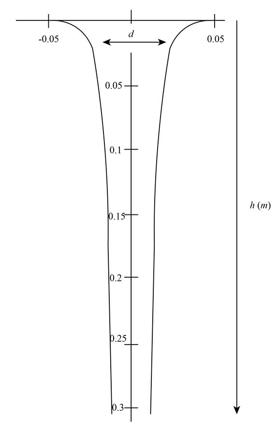
The profile of sprue diameter as function of its height.
Answer to Problem 5.71P
The profile of sprue diameter as function of its height is shown in Figure-A.
Explanation of Solution
Given data:
The diameter at top of the sprue is
The height of the sprue is
The diameter at bottom of the sprue is
Formula used:
The expression for the area is given as,
Here,
Calculation:
The relation between area and height can be given as,
Here,
Evaluate the above equation further,
In equation 1, take
Here, equation 1 becomes,
As the reference location for the height is not known, take
So, the location of surface at height from top surface is
Substitute the value in equation 2,
Further applying the boundary conditions,
At
Substitute the values in equation 3,
At
Substitute the values in equation 3,
Solve equation 4 and 5,
Substitute the value in equation 4,
Substitute the values in equation 3,
The graph further can be plotted between the diameter and sprue height using the above equation.

Figure- A Graph between diameter and height of the sprue
Conclusion:
Therefore, the profile of sprue diameter as function of its height is shown in Figure-A.
Want to see more full solutions like this?
Chapter 5 Solutions
Pearson eText for Manufacturing Processes for Engineering Materials -- Instant Access (Pearson+)
- I need to find m in R = mD from the image given. Do you really need to know what R and D is to find R. I was thinking geometrically we can find a relationship between R and D. D = R*cos(30). Then R = mD becomes m = R/D = 1/cos(30) = 1.1547. Is that correct?arrow_forwardQ1] B/ (16 Marks) To produce a lightweight epoxy part to provide thermal insulation. The available material are hollow glass beads for which the outside diameter is 1.6 mm and the wall thickness is 0.04 mm. Determine the weight and number of beads that must be added to the epoxy to produce a 0.5 kg of composite with a density of 0.65 g/cm³. The density of the glass is 2.5 g/cm³ and that of the epoxy is 1.25 g/cm³.arrow_forwardBelow is a projection of the inertia ellipsoid in the b1-b2 plane (b1 and b2 are unit vectors). All points on the ellipsoid surface represent moments of inertia in various directions. The distance R is related to the distance D such that R = md. Determine m.arrow_forward
- Below is a projection of the inertia ellipsoid in the b1-b2 plane (b1 and b2 are unit vectors). All points on the ellipsoid surface represent moments of inertia in various directions. Determine I_aa ( moment of inertia) for direction n_a (this is a unit vector).arrow_forwardThe problems are generally based on the following model: A particular spacecraft can be represented as a single axisymmetric rigid body B. Let n₂ be inertially fixed unit vectors; then, 6, are parallel to central, principal axes. To make the mathematics simpler, introduce a frame C where n₂ = ĉ₁ = b; initially. 6₁ Assume a mass distribution such that J =₁₁• B* •b₁ = 450 kg - m² I = b² •Ï¾˜ • b₂ = b¸ •Ï¾* •b¸ = 200 kg - m² K J-I C³ =r₁₁ = r₁₁arrow_forwardThe problems are generally based on the following model: A particular spacecraft can be represented as a single axisymmetric rigid body B. Let n₂ be inertially fixed unit vectors; then, 6, are parallel to central, principal axes. To make the mathematics simpler, introduce a frame C where n₂ = ĉ₁ = b; initially. 6₁ Assume a mass distribution such that J =₁₁• B* •b₁ = 450 kg - m² I = b² •Ï¾˜ • b₂ = b¸ •Ï¾* •b¸ = 200 kg - m² K J-I C³ =r₁₁ = r₁₁arrow_forward
- The problems are generally based on the following model: A particular spacecraft can be represented as a single axisymmetric rigid body B. Let n₂ be inertially fixed unit vectors; then, 6, are parallel to central, principal axes. To make the mathematics simpler, introduce a frame C where n₂ = ĉ₁ = b; initially. 6₁ Assume a mass distribution such that J =₁₁• B* •b₁ = 450 kg - m² I = b² •Ï¾˜ • b₂ = b¸ •Ï¾* •b¸ = 200 kg - m² K J-I C³ =r₁₁ = r₁₁arrow_forward##### Determine an example of a design of a compressed air system, which uses the criterion of speed for the design of the pipes (formula attached). The demands of flow rate, power as well as air velocity in the pipelines can be freely chosen. Sizing the compressor (flow, power...) Size reservoir required Setting the dryer Determine the amount of water withdrawn from the system due to air compression **With the attached formula you can choose the appropriate values of the unknownsarrow_forwardTo make an introduction to a report of a simple design of a compressed air system, which uses the criterion of speed, and not that of pressure drop, to determine the diameter of the pipes, where the capacity of the compressor and the demands of the equipment are expressed in flow.arrow_forward
- In an irrigation system, the following characteristics of the pipe network are available.• 100 meters of 4" PVC pipe, 3 gate valves• 500 meters of 3" PVC pipe, 4 gate valves• 200 meters of 2" H.G. pipe, 2 globe valves• 50 litres per second circulate in the pipes:Calculate:1. Total energy losses in meters.2. Leaks in pipes.3. Losses in accessories.4. Calculate the equivalent pipe of that system assuming only pipes without fittings.Solve the problem without artificial intelligence, solve by one of the expertsarrow_forwardLiquid water enters the boiler at 60 bar. Steam exits the boiler at 60 bar, 540°C and undergoes a throttling process to 40 bar before entering the turbine. Steam expands adiabatically through the turbine to 5 bar, 240°C, and then undergoes a throttling process to 1 bar before entering the condenser. Kinetic and potential energy effects can be ignored. Draw a Temperature-Entropy diagram and mark each of the states 2-5 on this diagram. Determine the power generated by the turbine, in kJ per kg of steam flowing. For the valves and the turbine, evaluate the rate of entropy production, each in kJ/K per kg of steam flowing.arrow_forwardFind the componenets of reactions at pins of A, B and D please show the detailed process and instructions for learning draw out all diagrams please and thank youarrow_forward
 Elements Of ElectromagneticsMechanical EngineeringISBN:9780190698614Author:Sadiku, Matthew N. O.Publisher:Oxford University Press
 Mechanics of Materials (10th Edition)Mechanical EngineeringISBN:9780134319650Author:Russell C. HibbelerPublisher:PEARSON
 Thermodynamics: An Engineering ApproachMechanical EngineeringISBN:9781259822674Author:Yunus A. Cengel Dr., Michael A. BolesPublisher:McGraw-Hill Education
 Control Systems EngineeringMechanical EngineeringISBN:9781118170519Author:Norman S. NisePublisher:WILEY
 Mechanics of Materials (MindTap Course List)Mechanical EngineeringISBN:9781337093347Author:Barry J. Goodno, James M. GerePublisher:Cengage Learning
 Engineering Mechanics: StaticsMechanical EngineeringISBN:9781118807330Author:James L. Meriam, L. G. Kraige, J. N. BoltonPublisher:WILEY


