
EBK STRUCTURAL ANALYSIS
6th Edition
ISBN: 9780357030974
Author: KASSIMALI
Publisher: VST
expand_more
expand_more
format_list_bulleted
Videos
Textbook Question
Chapter 5, Problem 54P
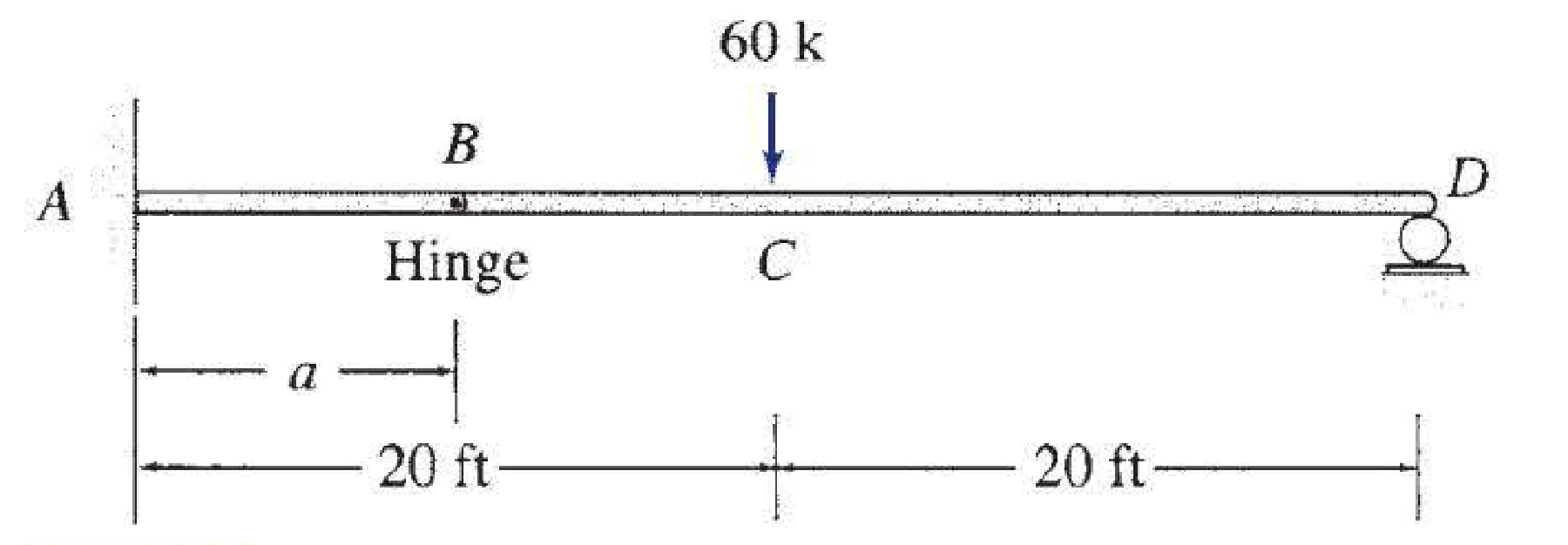
For the beam shown: (a) determine the distance a for which the maximum positive and negative bending moments in the beam are equal; and (b) draw the corresponding shear and bending moment diagrams for the beam.
Expert Solution & Answer

Trending nowThis is a popular solution!

Students have asked these similar questions
Directions: Show your solutions explicitly, I.e., do not just write the final answer. Always simplify and box your final
answer.
1. A wall footing is to be constructed on a clay soll 1.4 below the ground. The footing is to support a wall that
imposes a load of 130 kN per meter of wall length. Considering general shear failure, determine the following:
130 kN/m
4m
a. Footing width if the factor of safety is 3.
b. Ultimate bearing capacity if B = 0.95 m.
c. New factor of safety.
Y = 17.92 kN/m²
c = 14.5 kPa
$ -30°
2. A square footing shown has a dimension of 1.5 mx 1.5 m and has its bottom 2 m below the ground surface.
The groundwater table is located at a depth of 3 m below the ground surface. Assume a general shear failure.
Determine the following:
L
2 m
y = 16 kN/m³
c = 14.5 kPa
= 28°
3 m
1.5 m
Ysa1 = 18.5 kN/m³
a. Ultimate bearing capacity of the soll beneath the footing (in kPa).
b. Allowable bearing capacity if it has a factor of safety of 3 (in kPa).
C. Allowable load that the…
B2. For the truss below, determine all member forces. Hint: see the provided slide with the
problem set. P₁ = 12 kip and P₂ = 6 kip (20 pts).
P₁
16 ft
D
8 ft
8 ft
8 ft
B
K
E
8 ft
8 ft
8 ft
H
8 ft
В
G
1000
8 ft
14.1 A beam of rectangular cross section is 125 mm wide
and 200 mm deep. If the maximum bending moment
is 28.5 kN⚫m, determine (a) the maximum tensile and
compressive bending stress, and (b) the bending stress
25 mm from the top of the section.
14.2 A rectangular beam 50 mm wide and 100 mm deep is
subjected to bending. What bending moment will
cause a maximum bending stress of 137.9 MN/m²
(MPa)?
14.3 Determine the bending moment in a rectangular
beam 3 in. wide and 6 in. deep if the maximum bend-
ing stress is 15,000 psi.
Chapter 5 Solutions
EBK STRUCTURAL ANALYSIS
Ch. 5 - Prob. 1PCh. 5 - Prob. 2PCh. 5 - Prob. 3PCh. 5 - Prob. 4PCh. 5 - Prob. 5PCh. 5 - Prob. 6PCh. 5 - Prob. 7PCh. 5 - Prob. 8PCh. 5 - Prob. 9PCh. 5 - Prob. 10P
Ch. 5 - Prob. 11PCh. 5 - Determine the equations for shear and bending...Ch. 5 - Determine the equations for shear and bending...Ch. 5 - Determine the equations for shear and bending...Ch. 5 - Determine the equations for shear and bending...Ch. 5 - Determine the equations for shear and bending...Ch. 5 - Determine the equations for shear and bending...Ch. 5 - Determine the equations for shear and bending...Ch. 5 - 5.12 through 5.28 Determine the equations for...Ch. 5 - 5.12 through 5.28 Determine the equations for...Ch. 5 - 5.12 through 5.28 Determine the equations for...Ch. 5 - 5.12 through 5.28 Determine the equations for...Ch. 5 - 5.12 through 5.28 Determine the equations for...Ch. 5 - 5.12 through 5.28 Determine the equations for...Ch. 5 - 5.12 through 5.28 Determine the equations for...Ch. 5 - 5.12 through 5.28 Determine the equations for...Ch. 5 - 5.12 through 5.28 Determine the equations for...Ch. 5 - 5.12 through 5.28 Determine the equations for...Ch. 5 - 5.29 through 5.51 Draw the shear and bending...Ch. 5 - 5.29 through 5.51 Draw the shear and bending...Ch. 5 - 5.29 through 5.51 Draw the shear and bending...Ch. 5 - 5.29 through 5.51 Draw the shear and bending...Ch. 5 - 5.29 through 5.51 Draw the shear and bending...Ch. 5 - 5.29 through 5.51 Draw the shear and bending...Ch. 5 - 5.29 through 5.51 Draw the shear and bending...Ch. 5 - 5.29 through 5.51 Draw the shear and bending...Ch. 5 - 5.29 through 5.51 Draw the shear and bending...Ch. 5 - 5.29 through 5.51 Draw the shear and bending...Ch. 5 - 5.29 through 5.51 Draw the shear and bending...Ch. 5 - 5.29 through 5.51 Draw the shear and bending...Ch. 5 - 5.29 through 5.51 Draw the shear and bending...Ch. 5 - 5.29 through 5.51 Draw the shear and bending...Ch. 5 - 5.29 through 5.51 Draw the shear and bending...Ch. 5 - 5.29 through 5.51 Draw the shear and bending...Ch. 5 - 5.29 through 5.51 Draw the shear and bending...Ch. 5 - 5.29 through 5.51 Draw the shear and bending...Ch. 5 - 5.29 through 5.51 Draw the shear and bending...Ch. 5 - 5.29 through 5.51 Draw the shear and bending...Ch. 5 - 5.29 through 5.51 Draw the shear and bending...Ch. 5 - 5.29 through 5.51 Draw the shear and bending...Ch. 5 - 5.29 through 5.51 Draw the shear and bending...Ch. 5 - Draw the shear and bending moment diagrams for the...Ch. 5 - For the beam shown: (a) determine the distance a...Ch. 5 - For the beam shown: (a) determine the distance a...Ch. 5 - Prob. 55PCh. 5 - Prob. 56PCh. 5 - Prob. 57PCh. 5 - Prob. 58PCh. 5 - Prob. 59PCh. 5 - Prob. 60PCh. 5 - Prob. 61PCh. 5 - Prob. 62PCh. 5 - Prob. 63PCh. 5 - Prob. 64PCh. 5 - Prob. 65PCh. 5 - Prob. 66PCh. 5 - Prob. 67PCh. 5 - Prob. 68PCh. 5 - Prob. 69PCh. 5 - Prob. 70PCh. 5 - Prob. 71P
Knowledge Booster


Learn more about
Need a deep-dive on the concept behind this application? Look no further. Learn more about this topic, civil-engineering and related others by exploring similar questions and additional content below.Similar questions
- B3. For the Howe truss below, assume all members are pin connected and take P₁ = 5 kN and P₂ = 10 kN: a. Determine all member forces (16 pts). b. Use a section cut to verify your answers for members GF, GD, and CD (4 Pts) P₁ A H 500 8 0000 B 0000] 2 m m 2 m 3 m B E D marrow_forwardI need detailed help solving this exercise from homework of Engineering Mathematics II.I do not really understand how to do, please do it step by step, not that long but clear. Thank you!P.S.: Please do not use AI, thanks!arrow_forwardI need detailed help solving this exercise from homework of Engineering Mathematics II.I do not really understand how to do, please do it step by step, not that long but clear. Thank you!P.S.: Please do not use AI, thanks!arrow_forward
- I need detailed help solving this exercise from homework of Engineering Mathematics II.I do not really understand how to do, please do it step by step, not that long but clear. Thank you!P.S.: Please do not use AI, thanks!arrow_forwardI need detailed help solving this exercise from homework of Engineering Mathematics II.I do not really understand how to do, please do it step by step, not that long but clear. Thank you!P.S.: Please do not use AI, thanks!arrow_forwardI need detailed help solving this exercise from homework of Engineering Mathematics II.I do not really understand how to do, please do it step by step, not that long but clear. Thank you!P.S.: Please do not use AI, thanks!arrow_forward
- I need detailed help solving this exercise from homework of Engineering Mathematics II.I do not really understand how to do, please do it step by step, not that long but clear. Thank you!P.S.: Please do not use AI, thanks!arrow_forwardI need detailed help solving this exercise from homework of Engineering Mathematics II.I do not really understand how to do, please do it step by step, not that long but clear. Thank you!P.S.: Please do not use AI, thanks!arrow_forwardI need detailed help solving this exercise from homework of Engineering Mathematics II.I do not really understand how to do, please do it step by step, not that long but clear. Thank you!P.S.: Please do not use AI, thanks!arrow_forward
- B1.For the truss below, take P₁ = 4 kip and P₂ = 3 kip: a. Determine all member forces. Hint: first find zero-force members (16 pts). b. Use a section cut to verify your answers for members JI, BI, and BC (4 Pts) В 18 ft 6 ft H B 6 ft C 8 ft D p81 8 ft E 8 ft 6 ft F6ftarrow_forwardQ13: The line CD, C(xc, 6), D(6,yd), the point D is on the right of point C, the value of horizontal effect H(3,0) is on the right of point C, the vertical effect V(0, -2) right of H. the distance between projection of the points H, V is 5cm, Find: 1- The value of xc and yd. 2- The distance between projections of the points C, D. 3- The true length (T.L.) of CD. 4- The angles a and ẞ. 5- A point F in the middle of line CD, find F (xf, yf).arrow_forwardQ9: The straight line AB of true length (8) cm, having the following data: A (5, ya) & B (xb, yb), the point B is on the left of point A, the inclination of the line to the horizontal plane (H.P) is 30° (a) it Horizontal trace H (-3, 0), and point H is on the left of point A with distance (16) cm. Draw the Plan & Elevation of the line AB and determine the following: 1. The missed coordinates: ya, xb, yb. 2. The coordinates of the vertical trace (V). 3. The inclination of the line to the vertical plane (V.P) (B). 4. The distance between projections of the points A and Barrow_forward
arrow_back_ios
SEE MORE QUESTIONS
arrow_forward_ios
Recommended textbooks for you

 Principles of Foundation Engineering (MindTap Cou...Civil EngineeringISBN:9781337705028Author:Braja M. Das, Nagaratnam SivakuganPublisher:Cengage Learning
 Steel Design (Activate Learning with these NEW ti...Civil EngineeringISBN:9781337094740Author:Segui, William T.Publisher:Cengage Learning
 Principles of Foundation Engineering (MindTap Cou...Civil EngineeringISBN:9781305081550Author:Braja M. DasPublisher:Cengage Learning
 Residential Construction Academy: House Wiring (M...Civil EngineeringISBN:9781285852225Author:Gregory W FletcherPublisher:Cengage Learning
 Engineering Fundamentals: An Introduction to Engi...Civil EngineeringISBN:9781305084766Author:Saeed MoaveniPublisher:Cengage Learning
Principles of Foundation Engineering (MindTap Cou...
Civil Engineering
ISBN:9781337705028
Author:Braja M. Das, Nagaratnam Sivakugan
Publisher:Cengage Learning
Steel Design (Activate Learning with these NEW ti...
Civil Engineering
ISBN:9781337094740
Author:Segui, William T.
Publisher:Cengage Learning
Principles of Foundation Engineering (MindTap Cou...
Civil Engineering
ISBN:9781305081550
Author:Braja M. Das
Publisher:Cengage Learning
Residential Construction Academy: House Wiring (M...
Civil Engineering
ISBN:9781285852225
Author:Gregory W Fletcher
Publisher:Cengage Learning
Engineering Fundamentals: An Introduction to Engi...
Civil Engineering
ISBN:9781305084766
Author:Saeed Moaveni
Publisher:Cengage Learning
Introduction to Materials; Author: Industrial Heating;https://www.youtube.com/watch?v=R8EV8R8f5Tw;License: Standard Youtube License