
Concept explainers
Videos
Design a circuit to amplify the difference between two inputs by 2.5.
- (a) Use only one op amp.
- (b) Use two op amps.
(a)
Design an amplifier circuit that contains only one op amp to amplify the required difference between two inputs.
Explanation of Solution
Calculation:
The difference amplifier is drawn and it is shown in Figure 1.
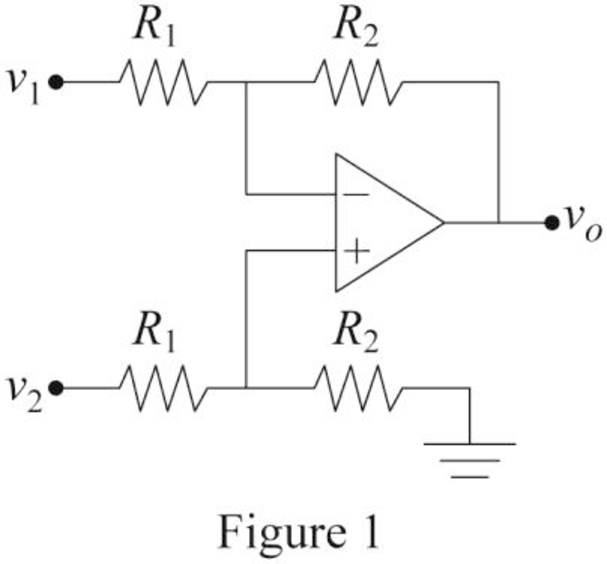
Write the expression for the output voltage
Consider that the required value of difference is 2.5.
Consider the expression for the output voltage of the difference amplifier with the difference of 2.5 between two inputs.
Compare Equations (1) and (2).
Choose the value of resistor
Substitute
Conclusion:
Thus, the required op amp circuit is designed and obtained values are
(b)
Design an amplifier circuit that contains two op amps to amplify the required difference between two inputs.
Explanation of Solution
Calculation:
Consider that the required value of difference is 2.5. To design the required circuit by cascading the inverting amplifier with summer amplifier.
The required difference amplifier with two op amps is drawn and it is shown in Figure 2.
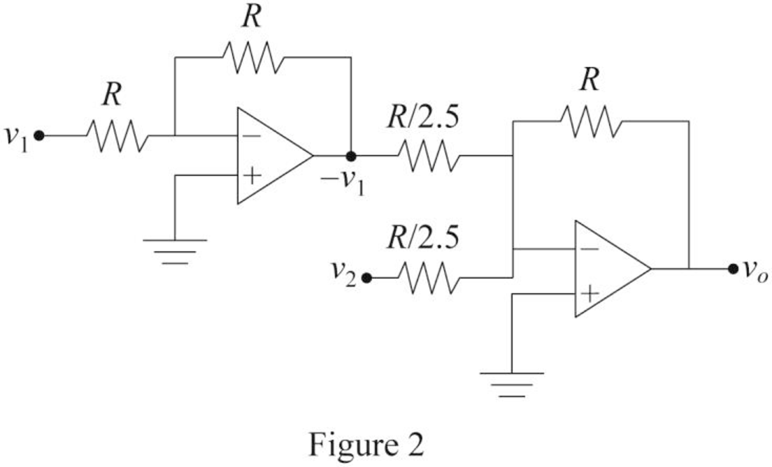
The output voltage of an inverting amplifier is,
Write the expression for the output voltage
Modify Equation (4).
Hence, Equation (4) satisfies the Equation (2).
Re-arrange Equation (4).
Here,
And
Choose the value of resistor R.
Substitute
Substitute
Substitute
Therefore, the value of resistors
Conclusion:
Thus, the required op amp circuit is designed and obtained values are
Want to see more full solutions like this?
Chapter 5 Solutions
EBK FUNDAMENTALS OF ELECTRIC CIRCUITS


- Circuits help please solve and explain. Question in images providedarrow_forward+ V 6.2 A 1.2 A S R 4 Ω Find the source voltage Vs 0.8 Aarrow_forwardDetermine i(t) for t≥ 0 given that the circuit below had been in steady state for a long time prior to t = 0. Also, I₁ = 1 5 A, R₁ =22, R2 =10 Q2, R3 = 32, R4 =7 2, and L=0.15 H. Also fill the table. m L ww R2 t = 0 R₁ 29 R3 R4 Time 0 iL(t) 0 8arrow_forward
- Find the Thévenin equivalent circuit for the portions of the networks in Figure external to the elements between points a and b. a R₁ 2002 I = 0.1 A 0° Xc : 32 Ω R2 = 6802 20 Ω фъarrow_forwardFind the Norton equivalent circuit for the network external to the elements between a and b for the networks in Figure. E1 = 120 V Z 0° R ww 10 Ω Xc XL · 000 802 802 ① I = 0.5 AZ 60° ZL barrow_forwardUsing superposition, determine the current through inductance XL for each network in Figure I = 0.3 A 60° XL 000 802 XC 502 Ω E 10 V0° =arrow_forward
- Find the Thévenin equivalent circuit for the portions of the networks in Figure external to the elements between points a and b. E = 20 VZ0° + R ww 2 ΚΩ Хо XL 000 6ΚΩ 3 ΚΩ b RLarrow_forwardWhat percentage of the full-load current of a thermally protected continuous-duty motor of more than one Hp can the trip current be, if the full-load current is 15 amperes? Ο 122 Ο 140 156 O 170arrow_forwardQ3arrow_forward
 Introductory Circuit Analysis (13th Edition)Electrical EngineeringISBN:9780133923605Author:Robert L. BoylestadPublisher:PEARSON
 Delmar's Standard Textbook Of ElectricityElectrical EngineeringISBN:9781337900348Author:Stephen L. HermanPublisher:Cengage Learning
 Programmable Logic ControllersElectrical EngineeringISBN:9780073373843Author:Frank D. PetruzellaPublisher:McGraw-Hill Education
 Fundamentals of Electric CircuitsElectrical EngineeringISBN:9780078028229Author:Charles K Alexander, Matthew SadikuPublisher:McGraw-Hill Education
 Electric Circuits. (11th Edition)Electrical EngineeringISBN:9780134746968Author:James W. Nilsson, Susan RiedelPublisher:PEARSON
 Engineering ElectromagneticsElectrical EngineeringISBN:9780078028151Author:Hayt, William H. (william Hart), Jr, BUCK, John A.Publisher:Mcgraw-hill Education,