
Fundamentals of Applied Electromagnetics (7th Edition)
7th Edition
ISBN: 9780133356816
Author: Fawwaz T. Ulaby, Umberto Ravaioli
Publisher: PEARSON
expand_more
expand_more
format_list_bulleted
Concept explainers
Videos
Textbook Question
Chapter 5, Problem 4P
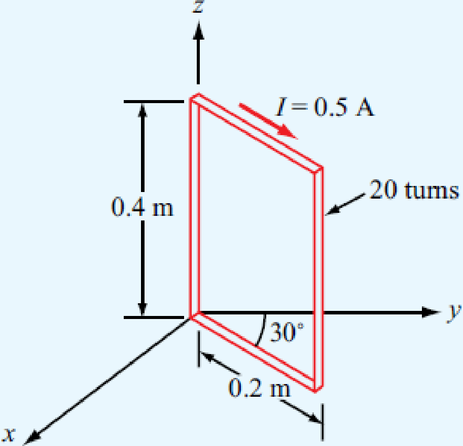
The rectangular loop shown in Fig. P5.4 consists of 20 closely wrapped turns and is hinged along the z axis. The plane of the loop makes an angle of 30° with the y axis, and the current in the windings is 0.5 A. What is the magnitude of the torque exerted on the loop in the presence of a uniform field
Expert Solution & Answer

Trending nowThis is a popular solution!

Students have asked these similar questions
A 50 transmission line is to be connected to a 72 load through a 1/4 quarter wave matching
transformer. (a) What must be the characteristic impedance of the transmission line that is
used to form the quarter wave transformer? (b) If the frequency of operation is 7 MHz and the
phase velocity through the quarter wave section is 2c/3, what is the length of the quarter wave
section? You may assume the transmission line forming the quarter wave section is lossless.
What is the SWR on a transmission line if the forward power arriving at the load is 5W but only
4.6W is dissipated by the load?
Please do not send the AI solution as it is full of errors. Solve the question yourself, please.
Q- If you have a unipolar winding stepper motor, draw the driver and the control circuit.
In subject (A stepper motor driver circuit and direction control using Arduino microcontroller)
Chapter 5 Solutions
Fundamentals of Applied Electromagnetics (7th Edition)
Ch. 5.1 - What are the major differences between the...Ch. 5.1 - Prob. 2CQCh. 5.1 - How is the direction of the magnetic moment of a...Ch. 5.1 - If one of two wires of equal length is formed into...Ch. 5.1 - An electron moving in the positive x direction...Ch. 5.1 - A proton moving with a speed of 2 106 m/s through...Ch. 5.1 - A charged particle with velocity u is moving in a...Ch. 5.1 - A horizontal wire with a mass per unit length of...Ch. 5.1 - A square coil of 100 turns and 0.5 m long sides is...Ch. 5.2 - Two infinitely long parallel wires carry currents...
Ch. 5.2 - Devise a right-hand rule for the direction of the...Ch. 5.2 - What is a magnetic dipole? Describe its magnetic...Ch. 5.2 - Prob. 6ECh. 5.2 - A wire carrying a current of 4 A is formed into a...Ch. 5.2 - Prob. 8ECh. 5.3 - What are the fundamental differences between...Ch. 5.3 - Prob. 9CQCh. 5.3 - Compare the utility of applying the BiotSavart law...Ch. 5.3 - Prob. 11CQCh. 5.3 - A current I flows in the inner conductor of a long...Ch. 5.3 - The metal niobium becomes a superconductor with...Ch. 5.5 - What are the three types of magnetic materials and...Ch. 5.5 - What causes magnetic hysteresis in ferromagnetic...Ch. 5.5 - Prob. 14CQCh. 5.5 - The magnetic vector M is the vector sum of the...Ch. 5.6 - With reference to Fig. 5-24, determine the single...Ch. 5.7 - Prob. 15CQCh. 5.7 - What is the difference between self-inductance and...Ch. 5.7 - Prob. 17CQCh. 5.7 - Use Eq. (5.89) to obtain an expression for B at a...Ch. 5 - An electron with a speed of 8 106 m/s is...Ch. 5 - When a particle with charge q and mass m is...Ch. 5 - The circuit shown in Fig. P5.3 uses two identical...Ch. 5 - The rectangular loop shown in Fig. P5.4 consists...Ch. 5 - In a cylindrical coordinate system, a 2 m long...Ch. 5 - Prob. 6PCh. 5 - Prob. 7PCh. 5 - Prob. 8PCh. 5 - The loop shown in Fig. P5.9 consists of radial...Ch. 5 - An infinitely long, thin conducting sheet defined...Ch. 5 - An infinitely long wire carrying a 25 A current in...Ch. 5 - Prob. 12PCh. 5 - Prob. 13PCh. 5 - Prob. 14PCh. 5 - A circular loop of radius a carrying current I1 is...Ch. 5 - Prob. 16PCh. 5 - Prob. 17PCh. 5 - Prob. 18PCh. 5 - Three long, parallel wires are arranged as shown...Ch. 5 - A square loop placed as shown in Fig. P5.20 has 2...Ch. 5 - Prob. 21PCh. 5 - Prob. 22PCh. 5 - Repeat Problem 5.22 for a current density J=zJ0er.Ch. 5 - In a certain conducting region, the magnetic field...Ch. 5 - Prob. 25PCh. 5 - Prob. 26PCh. 5 - Prob. 27PCh. 5 - A uniform current density given by J=zj0 (A/m2)...Ch. 5 - A thin current element extending between z = L/2...Ch. 5 - In the model of the hydrogen atom proposed by Bohr...Ch. 5 - Iron contains 8.5 1028 atoms/m3. At saturation,...Ch. 5 - The xy plane separates two magnetic media with...Ch. 5 - Given that a current sheet with surface current...Ch. 5 - In Fig. P5.34, the plane defined by x y = 1...Ch. 5 - The plane boundary defined by z = 0 separates air...Ch. 5 - Prob. 36PCh. 5 - Prob. 37PCh. 5 - A solenoid with a length of 20 cm and a radius of...Ch. 5 - Prob. 39PCh. 5 - The rectangular loop shown in Fig. P5.40 is...Ch. 5 - Determine the mutual inductance between the...
Knowledge Booster


Learn more about
Need a deep-dive on the concept behind this application? Look no further. Learn more about this topic, electrical-engineering and related others by exploring similar questions and additional content below.Similar questions
- 1- Draw the complete circuit diagram that illustrates the experiment concept as in figure 5 by showing the pins number. Show the following in your plot (Arduino board, steppermotor coils and the driver circuit). Note: The drawing should be on paper and not with artificial intelligence, please.arrow_forwardIn the circuit shown, find the following: 1) The current Ix. 2) The average power dissipated in the capacitor. 3) The total average power dissipated in the two resistors. 4) The average power of the independent voltage source and specify whether it is supplied or absorbed. 5) The total impedance seen from the terminals of the independent voltage source (Z=V/I). 20 -201 12/00V(+ 21 www 202arrow_forward2- If you have a unipolar winding stepper motor, draw the driver and the control circuit. Note: The drawing is on paper.arrow_forward
- Given the following reaction system, where Xo is the input, i.e u(t) = k₁ × Xo: $Xo -> x1; k1*Xo x2; k2*x1 x1 2 x2 ->%; k3*x2^2 x2 ->; k4*x2 Xo 1; k1 = 0.4 k2 4.5; k3 = 0.75 k4= 0.2 a) Build the model in Tellurium and run a simulation. Compute the Jacobian at steady state using the method getFull Jacobian(). Make sure you are at steady state! b) Write out the values for n and p c) Write out the differential equations. d) Write out the state space representation in terms of the rate constants etc. e) Compute the values in the Jacobian matrix from d) by substituting the values of the rate constants etc and any data you need from the simulation. f) Confirm that the Jacobian you get in e) is the same as the one computed from the simulation in a). g) Is the system stable or not? If you find an eigenvalue of zero, that means the system is marginally stable. You can get the eigenvalues using the tellurium method r.getFullEigenvalues()arrow_forwardSolve by Pen and Paper not using chatgpt or AIarrow_forwardYou just got a job at Shin-Etsu Chemical growing Si crystals with different dopants. Howmuch Ga needs to be added to 800 kg of Si melt to achieve a 5-10 Ω.cm (measured at midheight) Si CZ crystal with the following characteristics: height: 7 ft, width: 12 inchesdiameter. Assume, angular rotation 10 RPM, melt viscosity 0.1 poise, pull velocity 2mm/min.a. Generate a plot of the doping distribution throughout the length of the crystal (CGa vs. fs ).b. If a second crystal were to be pulled out of the melt without replenishment of silicon nordopant what would be the average resistivity of this crystal (or resistivity at mid height)arrow_forward
- DO NOT USE AI OR CHAT GPT NEED HANDWRITTEN SOLUTIONarrow_forward7. Complete the following problems for the circuit below. (a) When VDD = 120V, What is the voltage drop V1 across the 7Ω resistor? (b) If the voltage source VDD is set to obtain I1 = 2A, find the value of VDD. (c) If I1 = 100A, What is the value of I2arrow_forwarda) In terms of n and p, how many state variables and how many inputs can you see in the system below? dx1 =x12x2 + 9u1 dt dx2 =x1+x3+3u2 dt dx3 = 4x1 +5x2 - 12x3 dt b) Derive the state space representation for the above system c) Determine whether the system is stable or not.arrow_forward
- Circuit Logic. Match each statement to the proper circuit. All circuits have been drawn with a light (L) to represent the load, whether it is a motor, bell, light, or any other load. In addition, each switch is illustrated as a pushbutton whether it is a maintained switch, momentary contact switch, pushbutton, switch-on target, or any other type of switch.arrow_forwarda) In terms of n and p, how many state variables and how many inputs can you see in the system below? dx1 = 4x1 = x2 dt dx2 =-3x12x2 +U1 dt b) Derive the state space representation for the above system c) Determine whether the system is stable or not.arrow_forwardmatch each statement to the proper circuit. All circuits have been drawn with a light (L) to represent the load, whether it is a motor, bell, light or any other load. In addition, each switch is illustrated as a push button whether it is maintained switch, momentary contact switch, pushbutton, switch-on target, or any other type of switch.arrow_forward
arrow_back_ios
SEE MORE QUESTIONS
arrow_forward_ios
Recommended textbooks for you
 Introductory Circuit Analysis (13th Edition)Electrical EngineeringISBN:9780133923605Author:Robert L. BoylestadPublisher:PEARSON
 Delmar's Standard Textbook Of ElectricityElectrical EngineeringISBN:9781337900348Author:Stephen L. HermanPublisher:Cengage Learning
 Programmable Logic ControllersElectrical EngineeringISBN:9780073373843Author:Frank D. PetruzellaPublisher:McGraw-Hill Education
 Fundamentals of Electric CircuitsElectrical EngineeringISBN:9780078028229Author:Charles K Alexander, Matthew SadikuPublisher:McGraw-Hill Education
 Electric Circuits. (11th Edition)Electrical EngineeringISBN:9780134746968Author:James W. Nilsson, Susan RiedelPublisher:PEARSON
 Engineering ElectromagneticsElectrical EngineeringISBN:9780078028151Author:Hayt, William H. (william Hart), Jr, BUCK, John A.Publisher:Mcgraw-hill Education,
Introductory Circuit Analysis (13th Edition)
Electrical Engineering
ISBN:9780133923605
Author:Robert L. Boylestad
Publisher:PEARSON
Delmar's Standard Textbook Of Electricity
Electrical Engineering
ISBN:9781337900348
Author:Stephen L. Herman
Publisher:Cengage Learning
Programmable Logic Controllers
Electrical Engineering
ISBN:9780073373843
Author:Frank D. Petruzella
Publisher:McGraw-Hill Education
Fundamentals of Electric Circuits
Electrical Engineering
ISBN:9780078028229
Author:Charles K Alexander, Matthew Sadiku
Publisher:McGraw-Hill Education
Electric Circuits. (11th Edition)
Electrical Engineering
ISBN:9780134746968
Author:James W. Nilsson, Susan Riedel
Publisher:PEARSON
Engineering Electromagnetics
Electrical Engineering
ISBN:9780078028151
Author:Hayt, William H. (william Hart), Jr, BUCK, John A.
Publisher:Mcgraw-hill Education,
03 - The Cartesian coordinate system; Author: Technion;https://www.youtube.com/watch?v=hOgKEplCx5E;License: Standard YouTube License, CC-BY