
CONTROL SYSTEMS ENGINEERING - WILEYPLUS
7th Edition
ISBN: 9781119143277
Author: NISE
Publisher: WILEY
expand_more
expand_more
format_list_bulleted
Videos
Textbook Question
Chapter 5, Problem 27P
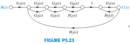
Using Mason’s rule, find the transfer function, T(s) = C(s)/R(s), for the system represented by
Figure P5.23. [Section: 5.5]
Expert Solution & Answer
Want to see the full answer?
Check out a sample textbook solution
Students have asked these similar questions
6.
Draw the isometric drawing for this problem(15%)
Please draw the section view of the following problems
7) Please draw the front, top and side view for the following object. Please cross this line out
Chapter 5 Solutions
CONTROL SYSTEMS ENGINEERING - WILEYPLUS
Ch. 5 - Prob. 1RQCh. 5 - Name three basic forms for interconnecting...Ch. 5 - For each of the forms in Question 2, state...Ch. 5 - Besides knowing the basic forms as discussed in...Ch. 5 - For a simple, second-order feedback control system...Ch. 5 - Prob. 6RQCh. 5 - Prob. 7RQCh. 5 - How are summing junctions shown on a signal-flow...Ch. 5 - If a forward path touched all closed loops, what...Ch. 5 - Name five representations of systems in state...
Ch. 5 - Prob. 11RQCh. 5 - Which form of the state-space representation leads...Ch. 5 - When the system matrix is diagonal, what...Ch. 5 - What terms lie along the diagonal for a system...Ch. 5 - Prob. 15RQCh. 5 - Prob. 16RQCh. 5 - For what kind of system would you use the observer...Ch. 5 - Describe state-vector transformations from the...Ch. 5 - Prob. 19RQCh. 5 - Prob. 20RQCh. 5 - Prob. 21RQCh. 5 - Find the closed-loop transfer function, T(s) =...Ch. 5 - Find the equivalent transfer function, T(s) =...Ch. 5 - Reduce the system shown in Figure P5.4 to a single...Ch. 5 - Reduce the block diagram shown in Figure P5.6 to a...Ch. 5 - Find the unity feedback system that is equivalent...Ch. 5 - 8. Given the block diagram of a system shown in...Ch. 5 - 9. Reduce the block diagram shown in Figure P5.9...Ch. 5 - Reduce the block diagram shown in Figure P5.10 to...Ch. 5 - 11. For the system shown in Figure P5.11, find the...Ch. 5 - 12. For the system shown in Figure P5.12, find the...Ch. 5 - Prob. 13PCh. 5 - For the system of Figure P5.14, find the value of...Ch. 5 - 15. For the system shown in Figure P5.15, find K...Ch. 5 - For the system of Figure P5.16, find the values of...Ch. 5 - Find the following for the system shown in Figure...Ch. 5 - 18. For the system shown in Figure P5.18, find ,...Ch. 5 - Prob. 19PCh. 5 - Prob. 20PCh. 5 - Find the transfer function G(s) = Eo(s)/T(s) for...Ch. 5 - Prob. 22PCh. 5 - Prob. 23PCh. 5 - State Space SS
24. Given the system below, draw a...Ch. 5 - Prob. 25PCh. 5 - Using Mason’s rule, find the transfer function,...Ch. 5 - Using Mason’s rule, find the transfer function,...Ch. 5 - Prob. 28PCh. 5 - Use block diagram reduction to find the transfer...Ch. 5 - State Space SS 30. Represent the following systems...Ch. 5 - Prob. 31PCh. 5 - State Space SS 32. Repeat Problem 31 and represent...Ch. 5 - Prob. 33PCh. 5 - Prob. 34PCh. 5 - Repeat Problem 34 for the system shown in Figure...Ch. 5 - Prob. 37PCh. 5 - State Space SS 38. Consider the rotational...Ch. 5 - Prob. 40PCh. 5 - Prob. 41PCh. 5 - State Space SS
42. Consider the subsystems shown...Ch. 5 - Prob. 43PCh. 5 - Prob. 44PCh. 5 - State Space SS
45. Diagonalize the following...Ch. 5 - Prob. 46PCh. 5 - Prob. 48PCh. 5 - Prob. 51PCh. 5 - Figure P5.33 shows a noninverting operational...Ch. 5 - Figure P5.34 shows the diagram of au inverting...Ch. 5 - Prob. 54PCh. 5 - A car active suspension system adds an active...Ch. 5 - Prob. 58PCh. 5 - Prob. 60PCh. 5 - Some medical procedures require the insertion of a...Ch. 5 - Prob. 62PCh. 5 - Prob. 64PCh. 5 - Prob. 65PCh. 5 - The purpose of an Automatic Voltage Regulator is...Ch. 5 - 68. Integrated circuits are manufactured through a...Ch. 5 - Prob. 69PCh. 5 - Prob. 72PCh. 5 - Prob. 73PCh. 5 - Assume ideal operational amplifiers in the circuit...Ch. 5 - Parabolic trough collector. Effective controller...
Knowledge Booster


Learn more about
Need a deep-dive on the concept behind this application? Look no further. Learn more about this topic, mechanical-engineering and related others by exploring similar questions and additional content below.Similar questions
- A 10-kg box is pulled along P,Na rough surface by a force P, as shown in thefigure. The pulling force linearly increaseswith time, while the particle is motionless att = 0s untilit reaches a maximum force of100 Nattimet = 4s. If the ground has staticand kinetic friction coefficients of u, = 0.6 andHU, = 0.4 respectively, determine the velocityof the A 1 0 - kg box is pulled along P , N a rough surface by a force P , as shown in the figure. The pulling force linearly increases with time, while the particle is motionless at t = 0 s untilit reaches a maximum force of 1 0 0 Nattimet = 4 s . If the ground has static and kinetic friction coefficients of u , = 0 . 6 and HU , = 0 . 4 respectively, determine the velocity of the particle att = 4 s .arrow_forwardCalculate the speed of the driven member with the following conditions: Diameter of the motor pulley: 4 in Diameter of the driven pulley: 12 in Speed of the motor pulley: 1800 rpmarrow_forward4. In the figure, shaft A made of AISI 1010 hot-rolled steel, is welded to a fixed support and is subjected to loading by equal and opposite Forces F via shaft B. Stress concentration factors K₁ (1.7) and Kts (1.6) are induced by the 3mm fillet. Notch sensitivities are q₁=0.9 and qts=1. The length of shaft A from the fixed support to the connection at shaft B is 1m. The load F cycles from 0.5 to 2kN and a static load P is 100N. For shaft A, find the factor of safety (for infinite life) using the modified Goodman fatigue failure criterion. 3 mm fillet Shaft A 20 mm 25 mm Shaft B 25 mmarrow_forward
- Please sovle this for me and please don't use aiarrow_forwardPlease sovle this for me and please don't use aiarrow_forward3. The cold-drawn AISI 1040 steel bar shown in the figure is subjected to a completely reversed axial load fluctuating between 28 kN in compression to 28 kN in tension. Estimate the fatigue factor of safety based on achieving infinite life (using Goodman line) and the yielding factor of safety. If infinite life is not predicted, estimate the number of cycles to failure. 25 mm + 6-mm D. 10 mmarrow_forward
- CORRECT AND DETAILED SOLUTION WITH FBD ONLY. I WILL UPVOTE 1. The truss shown is supported by hinge at A and cable at E.Given: H = 4m, S = 1.5 m, α = 75⁰, θ = 33⁰.Allowable tensile stress in cable = 64 MPa.Allowable compressive stress in all members = 120 MPaAllowable tensile stress in all members = 180 MPa1.Calculate the maximum permissible P, in kN, if the diameter of the cable is 20 mm.2.If P = 40 kN, calculate the required area (mm2) of member BC.3. If members have solid square section, with dimension 15 mm, calculate the maximum permissible P (kN) based on the allowable strength of member HI.ANSWERS: (1) 45.6 kN; (2) 83.71 mm2; (3) 171.76 kNarrow_forwardCORRECT AND DETAILED SOLUTION WITH FBD ONLY. I WILL UPVOTE 2: A wire 4 meters long is stretched horizontally between points 4 meters apart. The wire is 25 mm2 in cross-section with a modulus of elasticity of 200 GPa. A load W placed at the center of the wire produces a sag Δ.1.Calculate the tension (N) in the wire if sag Δ = 30 mm.2.Calculate the magnitude of W, in N, if sag Δ = 54.3 mm.3. If W is 60 N, what is the sag (in mm)?ANSWERS: (1) 562 N, (2) 100 N, (3) 45.8 Narrow_forwardCORRECT AND DETAILED SOLUTION WITH FBD ONLY. I WILL UPVOTE 4 : A cable and pulley system at D is used to bring a 230-kg pole (ACB) to a vertical position as shown. The cable has tensile force T and is attached at C. The length of the pole is 6.0 m, the outer diameter is d = 140 mm, and the wall thickness t = 12 mm. The pole pivots about a pin at A. The allowable shear stress in the pin is 60 MPa and the allowable bearing stress is 90 MPa. The diameter of the cable is 8 mm.1.Find the minimum diameter (mm) of the pin at A to support the weight of the pole in the position shown.2.Calculate the elongation (mm) of the cable CD.3.Calculate the vertical displacement of point C, in mm.ANSWERS: (1) 6 mm, (2) 1.186 mm, (3) 1.337 mm--arrow_forward
arrow_back_ios
SEE MORE QUESTIONS
arrow_forward_ios
Recommended textbooks for you
 Elements Of ElectromagneticsMechanical EngineeringISBN:9780190698614Author:Sadiku, Matthew N. O.Publisher:Oxford University Press
 Mechanics of Materials (10th Edition)Mechanical EngineeringISBN:9780134319650Author:Russell C. HibbelerPublisher:PEARSON
 Thermodynamics: An Engineering ApproachMechanical EngineeringISBN:9781259822674Author:Yunus A. Cengel Dr., Michael A. BolesPublisher:McGraw-Hill Education
 Control Systems EngineeringMechanical EngineeringISBN:9781118170519Author:Norman S. NisePublisher:WILEY
 Mechanics of Materials (MindTap Course List)Mechanical EngineeringISBN:9781337093347Author:Barry J. Goodno, James M. GerePublisher:Cengage Learning
 Engineering Mechanics: StaticsMechanical EngineeringISBN:9781118807330Author:James L. Meriam, L. G. Kraige, J. N. BoltonPublisher:WILEY
Elements Of Electromagnetics
Mechanical Engineering
ISBN:9780190698614
Author:Sadiku, Matthew N. O.
Publisher:Oxford University Press
Mechanics of Materials (10th Edition)
Mechanical Engineering
ISBN:9780134319650
Author:Russell C. Hibbeler
Publisher:PEARSON
Thermodynamics: An Engineering Approach
Mechanical Engineering
ISBN:9781259822674
Author:Yunus A. Cengel Dr., Michael A. Boles
Publisher:McGraw-Hill Education
Control Systems Engineering
Mechanical Engineering
ISBN:9781118170519
Author:Norman S. Nise
Publisher:WILEY
Mechanics of Materials (MindTap Course List)
Mechanical Engineering
ISBN:9781337093347
Author:Barry J. Goodno, James M. Gere
Publisher:Cengage Learning
Engineering Mechanics: Statics
Mechanical Engineering
ISBN:9781118807330
Author:James L. Meriam, L. G. Kraige, J. N. Bolton
Publisher:WILEY
Ficks First and Second Law for diffusion (mass transport); Author: Taylor Sparks;https://www.youtube.com/watch?v=c3KMpkmZWyo;License: Standard Youtube License