
Concept explainers
Videos
a.
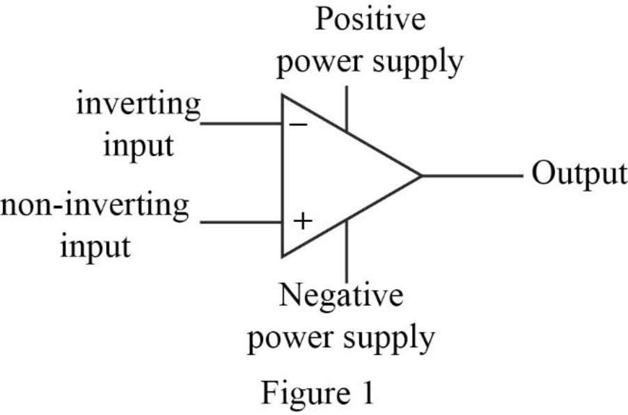
Label the five terminals in the operational amplifier.
a.
Explanation of Solution
Given data:
Refer to the given op amp circuit.
Discussion:
The five terminals of the op amp are labeled and it is shown in Figure 1.
Conclusion:
Thus, the five terminals in the operational amplifier are labeled.
b.
Mention the parameter that constraints the value of
b.
Answer to Problem 1P
The input resistance of the op amp constraints the value of
Explanation of Solution
Discussion:
The input resistance of an ideal op amp is infinite, which restricts the current
Conclusion:
Thus, the input resistance of the op amp constraints the value of
c.
Mention the parameter that constraints the value of
c.
Answer to Problem 1P
The open loop voltage gain of the op amp constraints the value of
Explanation of Solution
Discussion:
The open loop voltage gain of an ideal op amp is infinite, which constraints the difference between the voltage appear across the inverting and non-inverting terminal of the op amp to 0 V. Therefore,
Conclusion:
Thus, the open loop voltage gain of the op amp constraints the value of
d.
Find the value of voltage
d.
Answer to Problem 1P
The value of voltage
Explanation of Solution
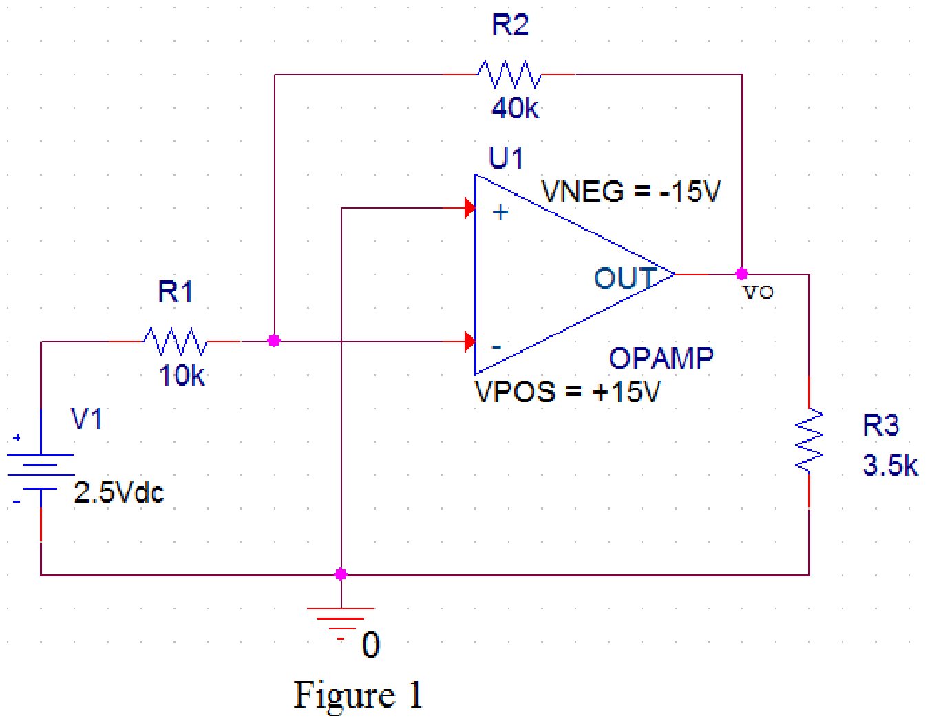
PSpice design:
Draw the given circuit in PSPICE as shown in Figure 2.
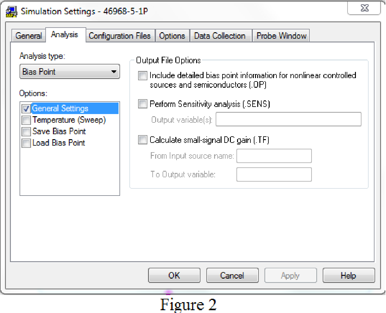
Provide the simulation settings as shown in Figure 3 to obtain output parameters.
After simulating the PSPICE circuit, the output voltage
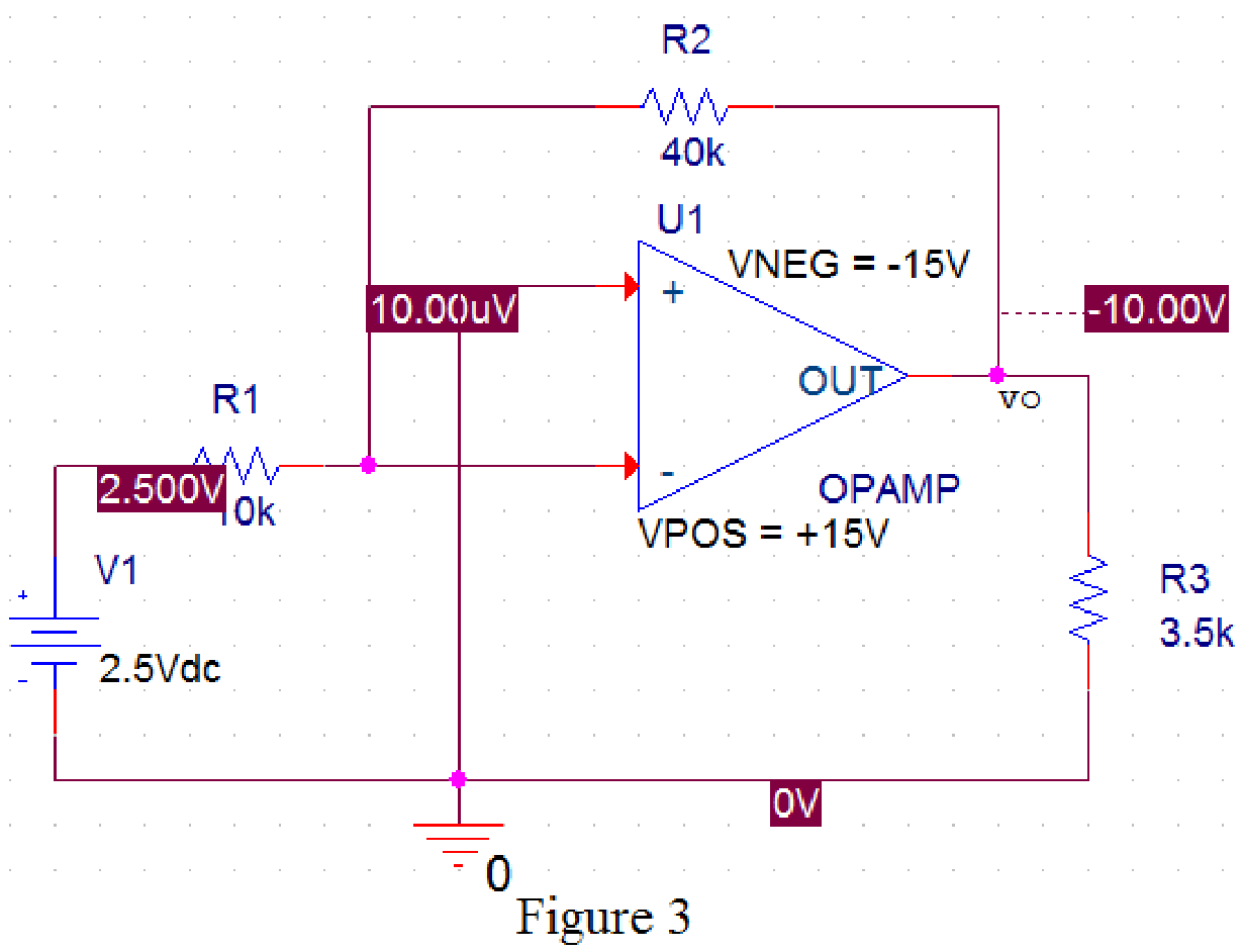
From Figure 4, the output voltage
Conclusion:
Thus, the value of voltage
Want to see more full solutions like this?
Chapter 5 Solutions
Electric Circuits, Student Value Edition Format: Unbound (saleable)
Additional Engineering Textbook Solutions
Concepts Of Programming Languages
Computer Science: An Overview (13th Edition) (What's New in Computer Science)
Electric Circuits. (11th Edition)
Starting Out with Python (4th Edition)
Modern Database Management
Java: An Introduction to Problem Solving and Programming (8th Edition)


- Use data sheet B on page 383 to draw the wiring diagram. Note: use only the number of contacts required. First 1. Wire the motor to operate in forward and reverse at 115 VAC.arrow_forwardB:A 20 MVA transformer which may be called upon to operate at 30% overload, feeds 11 KV busbars through a circuit breaker: other circuit breakers supply outgoing feeders. The transformer circuit breaker is equipped with 1000/5 A CTS and the feeder circuit breakers with 400/5 A CTS and all sets of CTs feed induction type over current relays. The relays on the feeder circuits breakers have a 125% plug setting, and 0.3 time setting. If 3 ph fault current of 5000 A flows from the transformer to one of the feeders, find the operating time of the feeder relay, the minimum plug setting of the transformer relay and its time setting assuming a discrimination time margin of 0.5 sec. Relays having the following characteristics for TMS=1 PSM T in sec. 2 3.6 5 10 15 20 10 6 3.9 2.8 2.2 2.1arrow_forward10.34 Determine the power readings of the two wattmetersshown in the circuit of Fig. P10.34 given that ZY = (15− j5) Warrow_forward
- 10.29 A 208-V (rms) balanced three-phase source supports twoloads connected in parallel. Each load is itself a balanced threephaseload. Determine the line current, given that load 1 is 12 kVAat pf 1 = 0.7 leading and load 2 is 18 kVA at pf 2 = 0.9 lagging.arrow_forward10.31 A 240-V (rms), 60-Hz Y-source is connected to a balancedthree-phase Y-load by four wires, one of which is the neutral wire.If the load is 400 kVA at pf old = 0.6 lagging, what size capacitorsshould be added to change the power factor to pf new = 0.95lagging?arrow_forwardCable A Cable A is a coaxial cable of constant cross section. The metal regions are shaded in grey and are made of copper. The solid central wire has radius a = 5mm, the outer tube inner radius b = 20mm and thickness t = 5mm. The dielectric spacer is Teflon, of relative permittivity &r = 2.1 and breakdown strength 350kV/cm. A potential difference of 1kV is applied across the conductors, with centre conductor positive and outer conductor earthed. Before undertaking any COMSOL simulations we'll first perform some theoretical analysis of Cable A based on the EN2076 lectures, to make sense of the simulations. Calculate the radial electric field of cable A at radial positions r b. Also calculate the maximum operating voltage of cable A, assuming a safety margin of ×2, and indicate where on the cable's cross section dielectric breakdown is most likely to occur.arrow_forward
- : For the gravity concrete dam shown in the figure, the following data are available: The factor of safety against sliding (F.S sliding)=1.2 Unit weight of concrete (Yconc)=24 KN/m³ - Neglect( Wave pressure, silt pressure, ice force and earth quake force) μ=0.65, (Ywater) = 9.81 KN/m³ Find factor of safety against overturning (F.S overturning) 6m3 80m Smarrow_forwardI need help checking if its correct -E1 + VR1 + VR4 – E2 + VR3 = 0 -------> Loop 1 (a) R1(I1) + R4(I1 – I2) + R3(I1) = E1 + E2 ------> Loop 1 (b) R1(I1) + R4(I1) - R4(I2) + R3(I1) = E1 + E2 ------> Loop 1 (c) (R1 + R3 + R4) (I1) - R4(I2) = E1 + E2 ------> Loop 1 (d) Now that we have loop 1 equation will procced on finding the equation of I2 current loop. However, a reminder that because we are going in a clockwise direction, it goes against the direction of the current. As such we will get an equation for the matrix that will be: E2 – VR4 – VR2 + E3 = 0 ------> Loop 2 (a) -R4(I2 – I1) -R2(I2) = -E2 – E3 ------> Loop 2 (b) -R4(I2) + R4(I1) - R2(I2) = -E2 – E3 -----> Loop 2 (c) R4(I1) – (R4 + R2)(I2) = -E2 – E3 -----> Loop 2 (d) These two equations will be implemented to the matrix formula I = inv(A) * b R11 R12 (R1 + R3 + R4) -R4 -R4 R4 + R2arrow_forward10.2 For each of the following groups of sources, determineif the three sources constitute a balanced source, and if it is,determine if it has a positive or negative phase sequence.(a) va(t) = 169.7cos(377t +15◦) Vvb(t) = 169.7cos(377t −105◦) Vvc(t) = 169.7sin(377t −135◦) V(b) va(t) = 311cos(wt −12◦) Vvb(t) = 311cos(wt +108◦) Vvc(t) = 311cos(wt +228◦) V(c) V1 = 140 −140◦ VV2 = 114 −20◦ VV3 = 124 100◦ Varrow_forward
 Introductory Circuit Analysis (13th Edition)Electrical EngineeringISBN:9780133923605Author:Robert L. BoylestadPublisher:PEARSON
 Delmar's Standard Textbook Of ElectricityElectrical EngineeringISBN:9781337900348Author:Stephen L. HermanPublisher:Cengage Learning
 Programmable Logic ControllersElectrical EngineeringISBN:9780073373843Author:Frank D. PetruzellaPublisher:McGraw-Hill Education
 Fundamentals of Electric CircuitsElectrical EngineeringISBN:9780078028229Author:Charles K Alexander, Matthew SadikuPublisher:McGraw-Hill Education
 Electric Circuits. (11th Edition)Electrical EngineeringISBN:9780134746968Author:James W. Nilsson, Susan RiedelPublisher:PEARSON
 Engineering ElectromagneticsElectrical EngineeringISBN:9780078028151Author:Hayt, William H. (william Hart), Jr, BUCK, John A.Publisher:Mcgraw-hill Education,