
Concept explainers
Videos
(a)
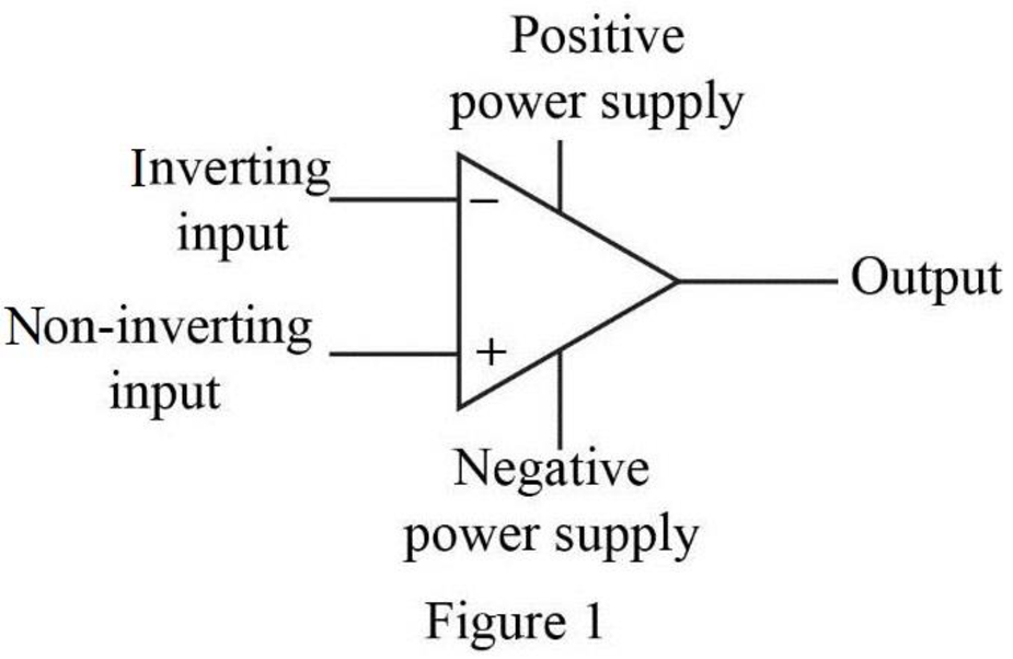
Label the five terminals in the operational amplifier.
(a)
Explanation of Solution
Given data:
Refer to Figure P5.1 in the textbook for the ideal op amp circuit.
Discussion:
The five terminals of the op amp are labeled as shown in Figure 1.
Conclusion:
Thus, the five op-amp terminals with their names are labeled as shown in Figure 1.
(b)
Mention the ideal op amp constraint that determines the value of
(b)
Answer to Problem 1P
The input resistance of the op amp constraints determines the value of
Explanation of Solution
Discussion:
The input resistance available at the input terminals will determines the current value
Conclusion:
Thus, the input resistance of the op amp constraints determines the value of
(c)
Mention the ideal op amp constraints that determines the value of
(c)
Answer to Problem 1P
The open loop voltage gain of the op amp constraints the value of
Explanation of Solution
Discussion:
The open loop voltage gain of an ideal op amp determines the value of
Conclusion:
Thus, the open loop voltage gain of the op amp constraints the value of
(d)
Find the value of voltage
(d)
Answer to Problem 1P
The value of voltage
Explanation of Solution
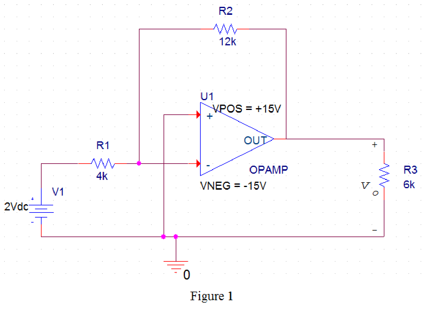
PSpice Simulation:
Draw the given circuit in PSPICE as shown in Figure 1.
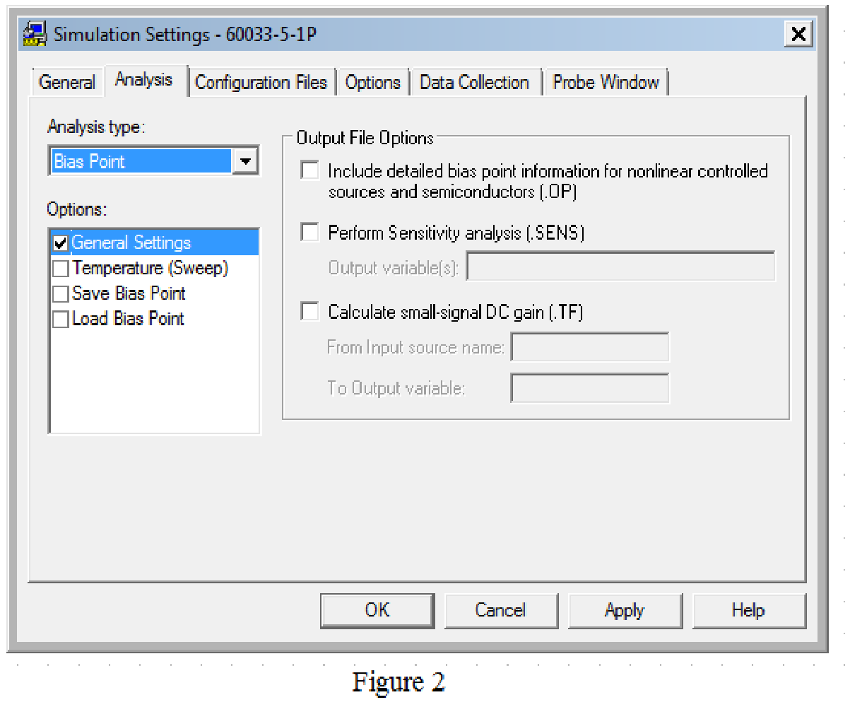
Provide the simulation settings as shown in Figure 2 to obtain output parameters.
After simulating the PSPICE circuit, the output voltage
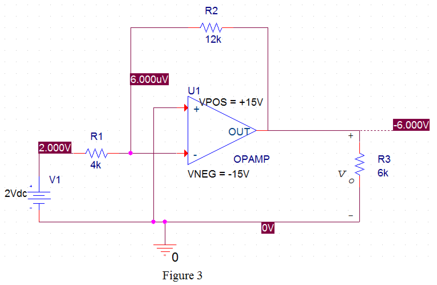
From Figure 3, the value of output voltage is
Conclusion:
Thus, the value of voltage
Want to see more full solutions like this?
Chapter 5 Solutions
Electric Circuits, Global Edition


- *10. For the network of Fig. 7.83, determine: a. Ip. b. VDS. c. VD. d. Vs. 20 V 2.2 ΚΩ ID -4 V IDSS = 4.5 mA VDS Vp = -5V 0.68 ΚΩarrow_forward4. a. Determine VDs for VGS = 0 V and ID = 6 mA using the characteristics of Fig. 6.11. b. Using the results of part (a), calculate the resistance of the JFET for the region ID = 0 to 6 mA for VGS = 0 V. c. Determine VDs for VGS = -1 V and ID = 3 mA. d. Using the results of part (c), calculate the resistance of the JFET for the region ID = 0 to 3 mA for VGS = -1 V. e. Determine VDs for VGS = -2 V and ID = 1.5 mA. f. Using the results of part (e), calculate the resistance of the JFET for the region ID 1.5 mA for VGS = -2 V. g. Defining the result of part (b) as ro, determine the resistance for VGS Eq. (6.1) and compare with the results of part (d). = 0 to = -1 V using h. Repeat part (g) for VGS = -2 V using the same equation, and compare the results with part (f). i. Based on the results of parts (g) and (h), does Eq. (6.1) appear to be a valid approximation?arrow_forwardQ1. Consider the unity feedback control system whose open-loop transfer function is: G(s): = 40(S+2) s(s+3)(s+1)(s + 10) ELECTRIC Ziegler-Nichols, By using second method of Ziegler- Nichols, calculate the PID, PI-D and I-PD parameters and make tuning for this parameters to get accepting response for the following system, then comp controllers? PARTME then compare your results for all types GINEARIarrow_forward
- Example 1: There is a transfer function for a second-order system given as follows. 120 G(s)= s²+12s+120 Find 5,,, T, T, T., and %OS.arrow_forward5. Please sketch a root locus manually for the following system. R(s) + E(s) C(s) k(s + 1) s² + 2s +2 Each branch in your root locus must be labeled with an arrow. Please answer the following questions. a. Is the closed-loop system stable as k is varying from 0 to co? Please find an answer to this question via root locus. b. What are finite zeros and poles? Are there infinite zeros? If so, how many?arrow_forward-5. Draw the connection diagram for two parallel transformers with (A-A) connected?arrow_forward
- HW_#6 HW_06.pdf EE 213-01 Assignments zm Rich LTI uah.instructure.com Z (MAE 272-01) (SP25) DYNAMICS b My Questions | bartleby ✓ Download → Info Page 1 > of 2 - ZOOM + 1) (5 pts) Note have to use nodal analysis at Vp and Vn. a) Determine Vout in the following ideal op-amp circuit. The power supplies supplying power to the op-amp have voltage values of ±15 volts (Vcc = +15 Volts, -VCC = -15Volts) b) Determine the value of RĘ that makes Vo, -15 Volts. c) What value of RF makes Vo = 0 Volts? out F out = 2V 1V 25K 10K 2V 1V 30K 100K RF 12K 12K + E น out E 2) (5 pts) Find Vout in the following circuit. Perform nodal analysis at nodes VN, VP and Va 20K Va 20K 10K 10K 1 V 2 V 5K Vout 15K Note: There is no restriction on the value for Vout for this problem. 3) (5 pts) For the Thevenin equivalent circuit shown, answer the following questions: 250 Ohms a 200 V ° b a) What load resistor results in maximum power delivered to that resistor? b) What is the maximum power delivered to the resistor in…arrow_forwardSuppose the Laplace transform of a causal signal x₁ (t) is given by X₁(s) s+2 s²+1 (a) What is the Fourier transform X₁ (w) of the signal? (b) Using the Laplace transform properties, find the Laplace transform of the following signal x2(t). x2(t) = e³ x₁(t−1)-4x₁(4) Note, you do not need to simplify the expression of X2(s). However, state whether it is possible to write X2(s) as a rational fraction (i.e. ratio of polynomials) in s.arrow_forwardConsider the following mechanical system. In the figure, y(t) denotes the displacement of the mass from its equilibrium position and u(t) denotes the force applied to the mass. k1 kz - y(t) -0000 0000 3 ► u(t) b a) Find the differential equation model of the system. b) Find the state-space model for the system. Write x, A, B, C and D clearly in your answer.arrow_forward
 Introductory Circuit Analysis (13th Edition)Electrical EngineeringISBN:9780133923605Author:Robert L. BoylestadPublisher:PEARSON
 Delmar's Standard Textbook Of ElectricityElectrical EngineeringISBN:9781337900348Author:Stephen L. HermanPublisher:Cengage Learning
 Programmable Logic ControllersElectrical EngineeringISBN:9780073373843Author:Frank D. PetruzellaPublisher:McGraw-Hill Education
 Fundamentals of Electric CircuitsElectrical EngineeringISBN:9780078028229Author:Charles K Alexander, Matthew SadikuPublisher:McGraw-Hill Education
 Electric Circuits. (11th Edition)Electrical EngineeringISBN:9780134746968Author:James W. Nilsson, Susan RiedelPublisher:PEARSON
 Engineering ElectromagneticsElectrical EngineeringISBN:9780078028151Author:Hayt, William H. (william Hart), Jr, BUCK, John A.Publisher:Mcgraw-hill Education,