EBK MINDTAP FOR HERMAN'S UNDERSTANDING
4th Edition
ISBN: 9781337798761
Author: Herman
Publisher: VST
expand_more
expand_more
format_list_bulleted
Textbook Question
Chapter 5, Problem 15RQ
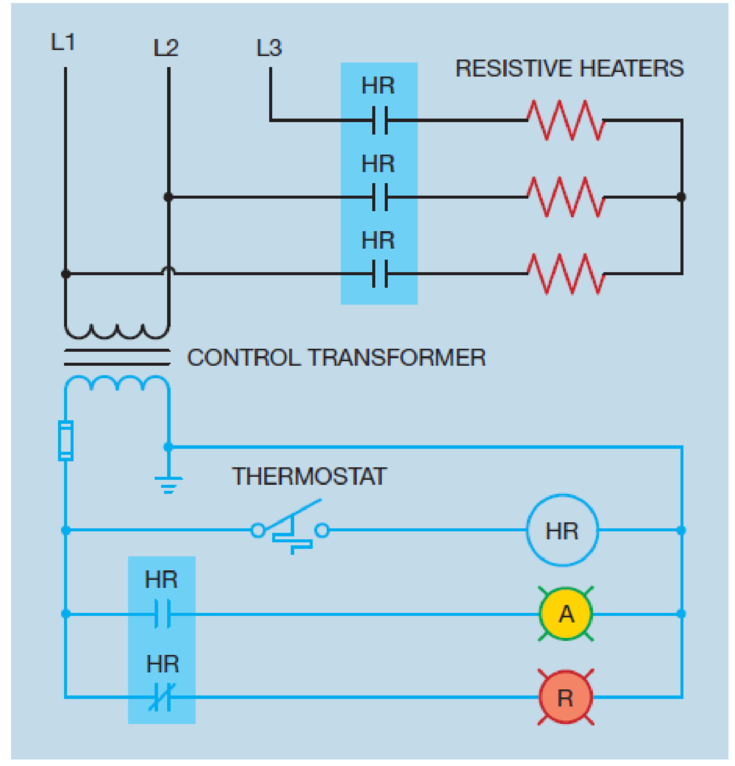
Refer to the circuit shown in Figure 5-29. In this circuit, the HR contactor is equipped with five contacts. Three are load contacts and two are auxiliary contacts. From looking at the schematic diagram, how is it possible to identify which contacts are the load contacts and which are the auxiliary contacts?

Figure 5-29 The contactor contains both load and auxiliary contacts.
Expert Solution & Answer
Want to see the full answer?
Check out a sample textbook solution
Students have asked these similar questions
13
F1
35
N = 37°.
=
Determine the resultant force on the eye bolt.
FR = (
+
FR magnitude:
FR coordinate direction angle a:
deg
FR coordinate direction angle ẞ`:
Ꭱ
deg
FR coordinate direction angle y:
deg
N
k) N
A hollow cylinder with inner radius of 30 mm and outer radius of 50 mm is heated at the inner surface at a rate of 10^5m^2W and dissipated heat by convection from outer surface into a fluid at 80∘C with h=400 m2 KW. There is no energy generation and thermal conductivity of the material is constant at 15mKW. Calculate the temperature of inside and outside surfaces of cylinder.
please read everything properly... Take 3 4 5 hrs but solve full accurate drawing on bond paper don't use chat gpt etc okk
Chapter 5 Solutions
EBK MINDTAP FOR HERMAN'S UNDERSTANDING
Ch. 5 - Prob. 1RQCh. 5 - Prob. 2RQCh. 5 - Explain the difference between auxiliary contacts...Ch. 5 - Prob. 4RQCh. 5 - What is optoisolation and what is its main...Ch. 5 - What pin numbers are connected to the coil of an...Ch. 5 - An 11-pin control relay contains three sets of...Ch. 5 - What is the purpose of the shading coil?
Ch. 5 - Refer to the circuit shown in Figure 5-29. Is the...Ch. 5 - What is the difference between a motor starter and...
Knowledge Booster
Learn more about
Need a deep-dive on the concept behind this application? Look no further. Learn more about this topic, mechanical-engineering and related others by exploring similar questions and additional content below.Similar questions
- An aircraft is flying trim stick-fixed at steady level flight with a speed of 80 m/s and at standard sea level conditions, where the air density is 1.225 kg/m3 . The ratio of the wings' surface area to the tail plane’s surface area is 10, the tail arm is 10 m and the wings’ mean aerodynamic chord length is 2 m. The ratio of the tail plane’s lift to the wings’ lift is -0.01 at that condition. The rest of the known data are given in the two tables at the end of the question. Justify any assumption that you make. a) Calculate the total lift and tail plane lift coefficients, the wings’ load and Calculate the down-wash angle and the tail plane angle of attackarrow_forwardAnswer a and barrow_forwardCơ cấu tạo hình được thiết kế để tạo ra hành trình cắt chậm và quay trở lại nhanh chóng với lưỡi gắn với con trượt tại C. Xác định vận tốc của khối con trượt C tại thời điểm 0=60° nếu liên kết AB đang quay với vận tốc góc 4 rad/s. 45° A. V 1.74(m/s) B. Vc=1.84(m/s) C. Vc = 1.24(m/s) D. Vc=1.64(m/s) 125 mm B = WAB 4 rad/s 300 mm Aarrow_forward
- please help solvearrow_forwardplease help solvearrow_forwardTwo springs and two masses are attached in a straight vertical line as shown in Figure Q3. The system is set in motion by holding the mass m₂ at its equilibrium position and pushing the mass m₁ downwards of its equilibrium position a distance 2 m and then releasing both masses. if m₁ = m₂ = 1 kg, k₁ = 3 N/m and k₂ = 2 N/m. www.m k₁ = 3 (y₁ = 0). m₁ = 1 k2=2 (y₂ = 0) |m₂ = 1 Y2 y 2 System in static equilibrium (Net change in spring length =32-31) System in motion Figure Q3 - Coupled mass-spring system Determine the equations of motion y₁(t) and y₂(t) for the two masses m₁ and m₂ respectively: Analytically (hand calculations)arrow_forward
- Two large tanks, each holding 100 L of liquid, are interconnected by pipes, with the liquid flowing from tank A into tank B at a rate of 3 L/min and from B into A at a rate of 1 L/min (see Figure Q1). The liquid inside each tank is kept well stirred. A brine solution with a concentration of 0.2 kg/L of salt flows into tank A at a rate of 6 L/min. The diluted solution flows out of the system from tank A at 4 L/min and from tank B at 2 L/min. If, initially, tank A contains pure water and tank B contains 20 kg of salt. A 6 L/min 0.2 kg/L x(t) 100 L 4 L/min x(0) = 0 kg 3 L/min B y(t) 100 L y(0) = 20 kg 2 L/min 1 L/min Figure Q1 - Mixing problem for interconnected tanks Determine the mass of salt in each tank at time t > 0: Analytically (hand calculations)arrow_forwardplease help solvearrow_forwardplease help solvearrow_forward
arrow_back_ios
SEE MORE QUESTIONS
arrow_forward_ios
Recommended textbooks for you
 Understanding Motor ControlsMechanical EngineeringISBN:9781337798686Author:Stephen L. HermanPublisher:Delmar Cengage Learning
 Electrical Transformers and Rotating MachinesMechanical EngineeringISBN:9781305494817Author:Stephen L. HermanPublisher:Cengage Learning
 Refrigeration and Air Conditioning Technology (Mi...Mechanical EngineeringISBN:9781305578296Author:John Tomczyk, Eugene Silberstein, Bill Whitman, Bill JohnsonPublisher:Cengage Learning
 Automotive TechnologyMechanical EngineeringISBN:9781337794213Author:ERJAVEC, Jack.Publisher:Cengage,
 Understanding Motor ControlsMechanical EngineeringISBN:9781305498129Author:Stephen L. HermanPublisher:Cengage Learning

Understanding Motor Controls
Mechanical Engineering
ISBN:9781337798686
Author:Stephen L. Herman
Publisher:Delmar Cengage Learning

Electrical Transformers and Rotating Machines
Mechanical Engineering
ISBN:9781305494817
Author:Stephen L. Herman
Publisher:Cengage Learning

Refrigeration and Air Conditioning Technology (Mi...
Mechanical Engineering
ISBN:9781305578296
Author:John Tomczyk, Eugene Silberstein, Bill Whitman, Bill Johnson
Publisher:Cengage Learning

Automotive Technology
Mechanical Engineering
ISBN:9781337794213
Author:ERJAVEC, Jack.
Publisher:Cengage,

Understanding Motor Controls
Mechanical Engineering
ISBN:9781305498129
Author:Stephen L. Herman
Publisher:Cengage Learning
Mod-01 Lec-16 Basics of Instrumentation; Author: nptelhrd;https://www.youtube.com/watch?v=qbKnW42ZM5c;License: Standard YouTube License, CC-BY