
Introductory Circuit Analysis; Laboratory Manual For Introductory Circuit Analysis Format: Kit/package/shrinkwrap
13th Edition
ISBN: 9780134297446
Author: Boylestad, Robert L.
Publisher: Prentice Hall
expand_more
expand_more
format_list_bulleted
Concept explainers
Videos
Textbook Question
Chapter 5, Problem 11P
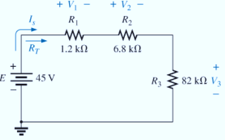
For the series configuration in Fig. 5.98, constructed using standard value resistors:
- Without making a single calculation, which resistive element will have the most voltage across it? Which will have the least?
- Which resistor will have the most impact on the total resistance and the resulting current? Find the total resistance and the current.
- Find the voltage across each element and review your response to part (a).
Expert Solution & Answer
Want to see the full answer?
Check out a sample textbook solution
Students have asked these similar questions
3. Find the transfer function and show all steps.
8. Determine the center frequency and Bandwidth of the following bandpass filter, show all steps.
7. Draw the circuit and show all steps.
Chapter 5 Solutions
Introductory Circuit Analysis; Laboratory Manual For Introductory Circuit Analysis Format: Kit/package/shrinkwrap
Ch. 5 - For each configuration in Fig. 5.88, find the...Ch. 5 - For each configuration in Fig. 5.89, find the...Ch. 5 - Find the total resistance RT for each...Ch. 5 - Find the total resistance RT for each...Ch. 5 - For each circuit board in Fig. 5.92, �nd the...Ch. 5 - For the circuit in Fig. 5.93, composed of standard...Ch. 5 - For each configuration in Fig. 5.94, determine the...Ch. 5 - Find the resistance R, given the ohmmeter reading...Ch. 5 - What is the ohmmeter reading for each...Ch. 5 - For the series configuration in Fig. 5.97,...
Ch. 5 - For the series configuration in Fig. 5.98,...Ch. 5 - Find the applied voltage necessary to develop the...Ch. 5 - For each network in Fig. 5.100, constructed of...Ch. 5 - For each configuration in Fig. 5.101, what are the...Ch. 5 - For each configuration of Fig. 5.102, find the...Ch. 5 - For the circuit in Fig. 5.103, constructed of...Ch. 5 - Find the unknown quantities for the circuit of...Ch. 5 - Find the unknown quantities for the circuit in...Ch. 5 - Eight holiday lights are connected in series as...Ch. 5 - For the conditions specified in Fig. 5.107,...Ch. 5 - Combine the series voltage sources in Fig. 5.108,...Ch. 5 - Determine the current I and its direction for each...Ch. 5 - Find {he unknown voltage source and resistor for...Ch. 5 - Using Kirchhoffs voltage law, find the unknown...Ch. 5 - Find the current I for the network of Fig. 5.112....Ch. 5 - Using Kirchhoffs voltage law, determine the...Ch. 5 - Using Kirchhoffs voltage law, find the unknown...Ch. 5 - Determine the values of the unknown resistors in...Ch. 5 - For the configuration in Fig. 5.116, with standard...Ch. 5 - Using the voltage divider rule, find the indicated...Ch. 5 - Using the voltage divider rule or Kirchhoffs...Ch. 5 - Using the voltage divider rule or Kirchhoffs...Ch. 5 - Using the information provided, find the unknown...Ch. 5 - Using the voltage divider rule, �nd the unknown...Ch. 5 - Design a voltage divider circuit that will permit...Ch. 5 - Design the voltage divider in Fig. 5.122 such that...Ch. 5 - Find the voltage across each resistor in Fig....Ch. 5 - Design the circuit in Fig. 5.124 such that...Ch. 5 - Determine the voltages Va,Vb, and Vab for the...Ch. 5 - Determine the current I (with direction) and the...Ch. 5 - For the network in Fig. 5.127 determine the...Ch. 5 - Given the information appearing in Fig. 5.128,...Ch. 5 - Determine the values of R1,R2,R3, and R4 for the...Ch. 5 - For the network in Fig. 5.130, determine the...Ch. 5 - For the integrated circuit in Fig. 5.131,...Ch. 5 - For the integrated circuit in Fig. 5.132,...Ch. 5 - Find the internal resistance of a battery that has...Ch. 5 - Find the voltage to the load (full-and conditions)...Ch. 5 - Determine the current through the circuit in Fig....Ch. 5 - Use the computer to verify the results of Example...Ch. 5 - Use the computer to verify the results of Example...Ch. 5 - Use the computer to verify the results of Example...
Additional Engineering Textbook Solutions
Find more solutions based on key concepts
How is the hydrodynamic entry length defined for flow in a pipe? Is the entry length longer in laminar or turbu...
Fluid Mechanics: Fundamentals and Applications
How are relationships between tables expressed in a relational database?
Modern Database Management
Porter’s competitive forces model: The model is used to provide a general view about the firms, the competitors...
Management Information Systems: Managing The Digital Firm (16th Edition)
The solid steel shaft AC has a diameter of 25 mm and is supported by smooth bearings at D and E. It is coupled ...
Mechanics of Materials (10th Edition)
What types of coolant are used in vehicles?
Automotive Technology: Principles, Diagnosis, And Service (6th Edition) (halderman Automotive Series)
A byte is made up of eight a. CPUs b. addresses c. variables d. bits
Starting Out with Java: From Control Structures through Objects (7th Edition) (What's New in Computer Science)
Knowledge Booster


Learn more about
Need a deep-dive on the concept behind this application? Look no further. Learn more about this topic, electrical-engineering and related others by exploring similar questions and additional content below.Similar questions
- 1. Find the transfer fucntion, show all steps.arrow_forward6. Determine the type of the filter in the following figure and calculate the cut off frequency fc, show all steps.arrow_forward5. Find the Transfer Function of the following circuit. Prove that it’s a low pass filter, show all steps.arrow_forward
- 2. Find the transfer function, show all steps.arrow_forwardI have this fsk function code: function [x]=fsk_encode(b,s,f0,f1,N,Fs,K) % b= bit sequence vector % s(1)= output level for 0 % s(2)= output level for 1 % N= length of bit sequence % Fs= Sampling frequency y=zeros(1,N*K); %Setup output vector %for each bit calculatee the rando samples for n=1:N for k=1:K t = (k - 1) / Fs; if(b(n)==0) y((n-1)*K+k)=cos(2*pi*f0*t); % pulse=0 else y((n-1)*K+k)=cos(2*pi*f1*t); % pulse=1 end end x=y; %set output end And this is another code that calls the function in order to get the power density spectrum: clc;clear; % EE 382 Communication Systems- Lab 8 % Plots the power spectrum of the ASK modulation % First specify some parameters N=256; % number of bits per realization M=100; % number of realizations in the ensemble T=0.001; % bit duration in seconds delf =2e+3; fc=10e+3; f0=fc-delf; f1=fc+delf; Fs=8*f1; % sampling frequency (this is needed to calibrate the frequency axis) K=(T/(1/Fs)); % Define arrays for bit sequences and sampled waveforms…arrow_forwardCalculate the parameters in the figurearrow_forward
- Write the angle expression form of first null beam width FNBW) for 2/2 dipole. for 즐, 꽃 3arrow_forwardThe circuit is in the DC steady state, So all transients are passed. What are the values of 1 and V, under those conditions. P 24v + + √2 АЛАД 42 4F 3.H ww 22 eee + 203 Varrow_forwardFind the value of Vc (t) for all I That is, the complete response including natural and forced responses.) АДДА 422 OV ДААД t = 0 3F + V(t) -arrow_forward
- 1.0 Half-power point (left) 0.5 Minor lobes Main lobe maximum direction Main lobe Half-power point (right) Half-power beamwidth (HP) Beamwidth between first nulls (BWFN) *Which of the following Lobes of an antenna Pattern 180 out of Phase the main Lobe ? And where are the ch other gems ?arrow_forwardThe normalized radiation intensity of an antenna is represented by U(0) = cos² (0) cos² (30), w/sr Find the a. half-power beamwidth HPBW (in radians and degrees) b. first-null beamwidth FNBW (in radians and degrees)arrow_forwardQ1/ Route the following flood hydrograph through a river reach for which storage duration constant = 10 hr and weighted factor = 0.25. At the start of the inflow flood, the outflow discharge is 60m³/s. Inflow (m/s) Time (hr) 140 60 100 0 4 8 12 16 120 80 40 20 Q2/ Answer the following: 1. Define water requirements and list the losses of irrigation. Q3/ Irrigation project with the following data: = 150 mm/m Root Zone Depth (RZD) = 1.1 m 15% of the net depth - Available Water PAD = 50%, Leaching Requirement Rainfall = 12 mm, = water Losses = 10% of the net depth. If the net water depth added after depletion of already available water, Calculate: gross irrigation water, and application efficiency. C= Carrow_forward
arrow_back_ios
SEE MORE QUESTIONS
arrow_forward_ios
Recommended textbooks for you
 EBK ELECTRICAL WIRING RESIDENTIALElectrical EngineeringISBN:9781337516549Author:SimmonsPublisher:CENGAGE LEARNING - CONSIGNMENT
 Delmar's Standard Textbook Of ElectricityElectrical EngineeringISBN:9781337900348Author:Stephen L. HermanPublisher:Cengage Learning
EBK ELECTRICAL WIRING RESIDENTIAL
Electrical Engineering
ISBN:9781337516549
Author:Simmons
Publisher:CENGAGE LEARNING - CONSIGNMENT
Delmar's Standard Textbook Of Electricity
Electrical Engineering
ISBN:9781337900348
Author:Stephen L. Herman
Publisher:Cengage Learning
Kirchhoff's Rules of Electrical Circuits; Author: Flipping Physics;https://www.youtube.com/watch?v=d0O-KUKP4nM;License: Standard YouTube License, CC-BY