
INTERNATIONAL EDITION---Engineering Mechanics: Statics, 14th edition (SI unit)
14th Edition
ISBN: 9780133918922
Author: Russell C. Hibbeler
Publisher: PEARSON
expand_more
expand_more
format_list_bulleted
Videos
Textbook Question
Chapter 4.4, Problem 34P
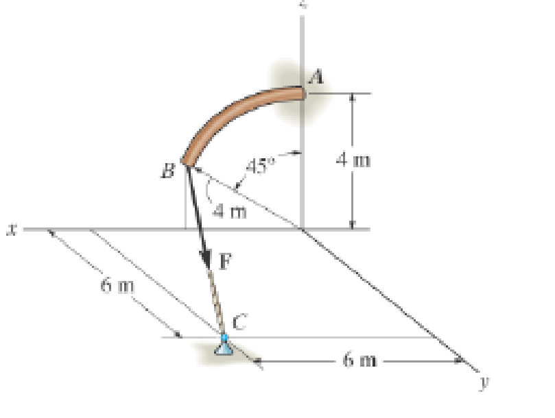
Determine the moment of the force of F = 600 N about point A.
Expert Solution & Answer
Want to see the full answer?
Check out a sample textbook solution
Students have asked these similar questions
can you please help me perform Visual Inspection and Fractography of the attatched image: Preliminary examination to identify the fracture origin, suspected fatigue striation, and corrosion evidences.
can you please help[ me conduct Causal Analysis (FTA) on the scenario attatched: FTA diagram which is a fault tree analysis diagram will be used to gain an overview of the entire path of failure from root cause to the top event (i.e., the swing’s detachment) and to identify interactions between misuse, material decay and inspection errors.
hi can you please help me in finding the stress intensity factor using a k-calcluator for the scenario attathced in the images.
Chapter 4 Solutions
INTERNATIONAL EDITION---Engineering Mechanics: Statics, 14th edition (SI unit)
Ch. 4.4 - P41. In each case, determine the moment of the...Ch. 4.4 - P42. In each case, set up the determinant to find...Ch. 4.4 - F41. Determine the moment of the force about point...Ch. 4.4 - F42. Determine the moment of the force about point...Ch. 4.4 - F43. Determine the moment of the force about point...Ch. 4.4 - Neglect the thickness of the member.Ch. 4.4 - F45. Determine the moment of the force about point...Ch. 4.4 - F46. Determine the moment of the force about point...Ch. 4.4 - F47. Determine the resultant moment produced by...Ch. 4.4 - F48. Determine the resultant moment produced by...
Ch. 4.4 - F49. Determine the resultant moment produced by...Ch. 4.4 - Express the result as a Cartesian vector.Ch. 4.4 - Express the result as a Cartesian vector.Ch. 4.4 - Express the result as a Cartesian vector.Ch. 4.4 - If A, B, and D are given vectors, prove the...Ch. 4.4 - Prove the triple scalar product identity A (B C)...Ch. 4.4 - Given the three nonzero vectors A, B and C, show...Ch. 4.4 - Determine the moment about point A of each of the...Ch. 4.4 - Determine the moment about point B of each of the...Ch. 4.4 - Find the moment of each force about point A and...Ch. 4.4 - Determine the moment of each of the three forces...Ch. 4.4 - Determine the moment of each of the three forces...Ch. 4.4 - Take FB = 40 lb, FC = 50 lb. Probs. 49/10Ch. 4.4 - If FB = 30 lb and FC = 45 lb, determine the...Ch. 4.4 - What is this moment?Ch. 4.4 - If x = 10 m, determine the position of the boom...Ch. 4.4 - What is the moment of this force about point B....Ch. 4.4 - Determine the moment of this force about point O....Ch. 4.4 - Determine the moment of each force about A. Which...Ch. 4.4 - If the man at B exerts a force of P = 30 lb on his...Ch. 4.4 - The mechanic reads the torque on the scale at B....Ch. 4.4 - Determine the torque (moment) MP that the applied...Ch. 4.4 - The tongs are used to grip the ends of the...Ch. 4.4 - The handle of the hammer is subjected to the force...Ch. 4.4 - In order to pull out the nail at B, the force F...Ch. 4.4 - The purpose of the fusee is to increase the...Ch. 4.4 - The tower crane is used to hoist the 2-Mg load...Ch. 4.4 - The tower crane is used to hoist a 2-Mg load...Ch. 4.4 - If the 1500-lb boom AB, the 200-lb cage BCD, and...Ch. 4.4 - If the 1500-lb boom AB, the 200-lb cage BCD, and...Ch. 4.4 - Determine the moment of the force F about point O....Ch. 4.4 - Express the result as a Cartesian vector.Ch. 4.4 - The force F = {400i 100j 700k} lb acts at the...Ch. 4.4 - The force F = {400i 100j 700k} lb acts at the end...Ch. 4.4 - Determine the moment of the force F about point P....Ch. 4.4 - The pipe assembly is subjected to the force of F =...Ch. 4.4 - The pipe assembly is subjected to the force of F =...Ch. 4.4 - Determine the moment of the force of F = 600 N...Ch. 4.4 - Determine the smallest force F that must be...Ch. 4.4 - Determine the coordinate direction angles , , of...Ch. 4.4 - Determine the moment of force F about point O. The...Ch. 4.4 - Determine the moment of the force F about the door...Ch. 4.4 - Determine the moment of the force F about the door...Ch. 4.4 - Determine the smallest force F that must be...Ch. 4.4 - Determine the smallest force F that must be...Ch. 4.4 - A 20-N horizontal force is applied perpendicular...Ch. 4.4 - The pipe assembly is subjected to the 80-N force....Ch. 4.4 - The pipe assembly is subjected to the 80-N force....Ch. 4.4 - A force F = {6i 2j + 1k}kN produces a moment of...Ch. 4.4 - The force F = {6i + 8j + 10k}N creates a moment...Ch. 4.4 - A force F having a magnitude of F = 100N acts...Ch. 4.4 - Force F acts perpendicular to the inclined plane....Ch. 4.4 - Force F acts perpendicular to the inclined plane....Ch. 4.4 - Strut AB of the 1-m-diameter hatch door exerts a...Ch. 4.4 - Using a ring collar, the 75-N force can act in the...Ch. 4.5 - P43. In each case, determine the resultant moment...Ch. 4.5 - P44. In each case, set up the determinant needed...Ch. 4.5 - F413. Determine the magnitude of the moment of the...Ch. 4.5 - F414. Determine the magnitude of the moment of the...Ch. 4.5 - Prob. 15FPCh. 4.5 - F416. Determine the magnitude of the moment of the...Ch. 4.5 - Express the result as a Cartesian vector.Ch. 4.5 - Prob. 18FPCh. 4.5 - The lug nut on the wheel of the automobile is to...Ch. 4.5 - Solve Prob. 4-52 if the cheater pipe AB is slipped...Ch. 4.5 - The A-frame is being hoisted into an upright...Ch. 4.5 - The A-frame is being hoisted into an upright...Ch. 4.5 - Determine the magnitude of the moments of the...Ch. 4.5 - Determine the moment of this force F about an axis...Ch. 4.5 - The board is used to hold the end of a four-way...Ch. 4.5 - The board is used to hold the end of a four-way...Ch. 4.5 - The A-frame is being hoisted into an upright...Ch. 4.5 - Determine the magnitude of the moment of the force...Ch. 4.5 - Determine the magnitude of the moment of the force...Ch. 4.5 - Determine the magnitude of the moment of the force...Ch. 4.5 - A horizontal force of F = {50i} N is applied...Ch. 4.5 - Determine the magnitude of the horizontal force F...Ch. 4.5 - The force of F = 30 N acts on the bracket as...Ch. 4.6 - F419. Determine the resultant couple moment acting...Ch. 4.6 - F420. Determine the resultant couple moment acting...Ch. 4.6 - Determine the magnitude of F so that the resultant...Ch. 4.6 - Determine the couple moment acting on the beam.Ch. 4.6 - Determine the resultant couple moment acting on...Ch. 4.6 - Determine the couple moment acting on the pipe...Ch. 4.6 - A clockwise couple M = 5 N m is resisted by the...Ch. 4.6 - A twist of 4 N m is applied to the handle of the...Ch. 4.6 - If the resultant couple of the three couples...Ch. 4.6 - Two couples act on the beam. If F = 125 lb,...Ch. 4.6 - Two couples act on the beam. Determine the...Ch. 4.6 - Determine the magnitude of the couple forces F so...Ch. 4.6 - The ends of the triangular plate are subjected to...Ch. 4.6 - The man tries to open the valve by applying the...Ch. 4.6 - If the valve can be opened with a couple moment of...Ch. 4.6 - Determine the magnitude of F so that the resultant...Ch. 4.6 - Two couples act on the beam as shown. If F = 150...Ch. 4.6 - Two couples act on the beam as shown. Determine...Ch. 4.6 - Two couples act on the frame. If the resultant...Ch. 4.6 - Two couples act on the frame. If d = 4 ft...Ch. 4.6 - Two couples act on the frame. If d = 4 ft,...Ch. 4.6 - Express the moment of the couple acting on the...Ch. 4.6 - If M1 = 180 lb ft, M2 = 90 lb ft, and M3 = 120...Ch. 4.6 - Determine the magnitudes of couple moments M1, M2,...Ch. 4.6 - The gears are subjected to the couple moments...Ch. 4.6 - Prob. 86PCh. 4.6 - Determine the resultant couple moment of the two...Ch. 4.6 - Express the moment of the couple acting on the...Ch. 4.6 - In order to turn over the frame, a couple moment...Ch. 4.6 - Express the moment of the couple acting on the...Ch. 4.6 - If the couple moment acting on the pipe has a...Ch. 4.6 - If F = 80 N, determine the magnitude and...Ch. 4.6 - If the magnitude of the couple moment acting on...Ch. 4.6 - Express the moment of the couple acting on the rod...Ch. 4.6 - If F1 = 100 N, F2 = 120 N, and F3 = 80 N,...Ch. 4.6 - Prob. 96PCh. 4.7 - P45. In each case, determine the x and y...Ch. 4.7 - Replace the leading system by an equivalent...Ch. 4.7 - Prob. 26FPCh. 4.7 - Replace the loading system by an equivalent...Ch. 4.7 - Replace the loading system by an equivalent...Ch. 4.7 - Replace the loading system by an equivalent...Ch. 4.7 - Replace the loading system by an equivalent...Ch. 4.7 - Replace the force system by an equivalent...Ch. 4.7 - Replace the force system by an equivalent...Ch. 4.7 - Replace the force system acting on the beam by an...Ch. 4.7 - Replace the force system acting on the beam by an...Ch. 4.7 - Replace the loading system acting on the beam by...Ch. 4.7 - Replace the loading system acting on the post by...Ch. 4.7 - Replace the loading system acting on the post by...Ch. 4.7 - Replace the force system acting on the post by a...Ch. 4.7 - Replace the force system acting on the frame by an...Ch. 4.7 - The forces F1 = {4i + 2j 3k) kN and F2 = {3i 4j...Ch. 4.7 - A biomechanical model of the lumbar region of the...Ch. 4.7 - Replace the force system by an equivalent...Ch. 4.7 - Replace the loading by an equivalent resultant...Ch. 4.7 - Replace the force of F = 80 N acting on the pipe...Ch. 4.7 - The belt passing over the pulley is subjected to...Ch. 4.7 - The belt passing over the pulley is subjected to...Ch. 4.8 - P46. In each case, determine the x and y...Ch. 4.8 - P47. In each case, determine the resultant force...Ch. 4.8 - Replace the loading system by an equivalent...Ch. 4.8 - Replace the loading system by an equivalent...Ch. 4.8 - Replace the loading system by an equivalent...Ch. 4.8 - Replace the loading system by an equivalent...Ch. 4.8 - Replace the loading shown by an equivalent single...Ch. 4.8 - Replace the loading shown by an equivalent single...Ch. 4.8 - The weights of the various components of the truck...Ch. 4.8 - The weights of the various components of the truck...Ch. 4.8 - Prob. 115PCh. 4.8 - Prob. 116PCh. 4.8 - Replace the loading acting on the beam by a single...Ch. 4.8 - Replace the loading acting on the beam by a single...Ch. 4.8 - Replace the loading on the frame by a single...Ch. 4.8 - Replace the loading on the frame by a single...Ch. 4.8 - Replace the loading on the frame by a single...Ch. 4.8 - Replace the force system acting on the post by a...Ch. 4.8 - Replace the force system acting on the post by a...Ch. 4.8 - Replace the parallel force system acting on the...Ch. 4.8 - Replace the force and couple system acting on the...Ch. 4.8 - Replace the force and couple system acting on the...Ch. 4.8 - Prob. 127PCh. 4.8 - Determine the magnitudes of FA and FB so that the...Ch. 4.8 - The tube supports the four parallel forces....Ch. 4.8 - The building slab is subjected to four parallel...Ch. 4.8 - The building slab is subjected to four parallel...Ch. 4.8 - If FA= 40 kN and FB = 35 kN, determine the...Ch. 4.8 - Prob. 133PCh. 4.8 - Replace the two wrenches and the force, acting on...Ch. 4.8 - Replace the force system by a wrench and specify...Ch. 4.8 - Replace the five forces acting on the plate by a...Ch. 4.8 - Replace the three forces acting on the plate by a...Ch. 4.9 - Determine the resultant force and specify where it...Ch. 4.9 - Determine the resultant force and specify where it...Ch. 4.9 - Determine the resultant force and specify where it...Ch. 4.9 - Determine the resultant force and specify where it...Ch. 4.9 - Determine the resultant force and specify where it...Ch. 4.9 - Determine the resultant force and specify where it...Ch. 4.9 - Replace the loading by an equivalent resultant...Ch. 4.9 - Replace the distributed loading with an equivalent...Ch. 4.9 - Replace the loading by an equivalent resultant...Ch. 4.9 - Currently eighty-five percent of all neck injuries...Ch. 4.9 - Replace the distributed loading by an equivalent...Ch. 4.9 - Replace this loading by an equivalent resultant...Ch. 4.9 - The distribution of soil loading on the bottom of...Ch. 4.9 - Replace the loading by an equivalent resultant...Ch. 4.9 - Replace the distributed loading by an equivalent...Ch. 4.9 - Determine the length b of the triangular load and...Ch. 4.9 - The form is used to cast a concrete wall having a...Ch. 4.9 - Prob. 149PCh. 4.9 - Replace the loading by an equivalent force and...Ch. 4.9 - Prob. 151PCh. 4.9 - Replace the loading by an equivalent resultant...Ch. 4.9 - Replace the leading by a single resultant force,...Ch. 4.9 - Replace the distributed loading by an equivalent...Ch. 4.9 - Prob. 155PCh. 4.9 - Determine the length b of the triangular load and...Ch. 4.9 - Determine the equivalent resultant force and...Ch. 4.9 - Determine the magnitude of the equivalent...Ch. 4.9 - The distributed load acts on the shaft as shown....Ch. 4.9 - Replace the distributed loading with an equivalent...Ch. 4.9 - Prob. 161PCh. 4.9 - Wet concrete exerts a pressure distribution along...Ch. 4.9 - and mass center at G. If the maximum moment that...Ch. 4.9 - R42. Replace the force F having a magnitude of F =...Ch. 4.9 - Determine the moment of this force about the...Ch. 4.9 - Determine the magnitude of the couple forces so...Ch. 4.9 - Prob. 5RPCh. 4.9 - R46. Replace the force system acting on the frame...Ch. 4.9 - Determine the equivalent resultant force and...Ch. 4.9 - R48. Replace the distributed loading by an...
Knowledge Booster


Learn more about
Need a deep-dive on the concept behind this application? Look no further. Learn more about this topic, mechanical-engineering and related others by exploring similar questions and additional content below.Similar questions
- Hi, can you please help me .Identify and justify suitable analytical techniques of the scenario below, bearing in mind the kinds of information being handled to reach a conclusion (methodology). A child swing set was discovered to have failed at the fixing at the top of the chains connecting the seat to the top of the swing set. A 12 mm threaded steel bolt, connecting the shackle to the top beam, failed at the start of the threaded region on the linkage closest to the outside side of the swing set . The linkage and bolts were made of electro galvanised mild steel . The rigid bar chain alternatives and fixings were of the same material and appeared to be fitted in accordance with guidelines. The yield strength of the steel used is 260 MPa and the UTS is 380 MPa. The bolt that failed was threaded using a standard thread with a pitch (distance between threads) of 1.75 mm and a depth of approximately 1.1 mm. The swing set in question had been assigned to ‘toddlers’ with the application of…arrow_forwardHi, can you please define and calculate the failure mode of the linkage that failed on the swing (images added) : A child swing set was discovered to have failed at the fixing at the top of the chains connecting the seat to the top of the swing set. A 12 mm threaded steel bolt, connecting the shackle to the top beam, failed at the start of the threaded region on the linkage closest to the outside side of the swing set . The linkage and bolts were made of electro galvanised mild steel . The rigid bar chain alternatives and fixings were of the same material and appeared to be fitted in accordance with guidelines. The yield strength of the steel used is 260 MPa and the UTS is 380 MPa. The bolt that failed was threaded using a standard thread with a pitch (distance between threads) of 1.75 mm and a depth of approximately 1.1 mm. The swing set in question had been assigned to ‘toddlers’ with the application of a caged-type seat. However, the location was within the play area not…arrow_forwardPage 11-68. The rectangular plate shown is subjected to a uniaxial stress of 2000 psi. Compute the shear stress and the tensile developed on a plane forming an angle of 30° with the longitud axis of the member. (Hint: Assume a cross-sectional area of unity) 2000 psi 2000 psi hparrow_forward
- 11-70. A shear stress (pure shear) of 5000 psi exists on an element. (a) Determine the maximum tensile and compressive stresses caused in the element due to this shear. (b) Sketch the element showing the planes on which the maximum tensile and compressive stresses act.arrow_forward11-20. An aluminum specimen of circular cross section, 0.50 in. in diameter, ruptured under a tensile load of 12,000 lb. The plane of failure was found to be at 48° with a plane perpendicular to the longitudinal axis of the specimen. (a) Compute the shear stress on the failure plane. (b) Compute the maximum tensile stress. (c) Compute the tensile stress on the failure plane. hparrow_forwardA long flat steel bar 13 mm thick and 120 mm wide has semicircular grooves as shown and carries a tensile load of 50 kN Determine the maximum stress if plate r= 8mm r=21mm r=38mmarrow_forward
- Problem 13: F₁ = A =250 N 30% Determine the moment of each of the three forces about point B. F₂ = 300 N 60° 2 m -3 m B 4 m F3=500 Narrow_forward3 kN 3 kN 1.8 kN/m 80 mm B 300 mm D an 1.5 m-1.5 m--1.5 m- PROBLEM 5.47 Using the method of Sec. 5.2, solve Prob. 5.16 PROBLEM 5.16 For the beam and loading shown, determine the maximum normal stress due to bending on a transverse section at C.arrow_forward300 mm 3 kN 3 kN 450 N-m D E 200 mm 300 mm PROBLEM 5.12 Draw the shear and bending-moment diagrams for the beam and loading shown, and determine the maximum absolute value (a) of the shear, (b) of the bending moment.arrow_forward
- CORRECT AND DETAILED SOLUTION WITH FBD ONLY. I WILL UPVOTE THANK YOU. CORRECT ANSWER IS ALREADY PROVIDED. I REALLY NEED FBD. The cantilevered spandrel beam shown whose depth tapers from d1 to d2, has a constant width of 120mm. It carries a triangularly distributed end reaction.Given: d1 = 600 mm, d2 = 120 mm, L = 1 m, w = 100 kN/m1. Calculate the maximum flexural stress at the support, in kN-m.2. Determine the distance (m), from the free end, of the section with maximum flexural stress.3. Determine the maximum flexural stress in the beam, in MPa.ANSWERS: (1) 4.630 MPa; (2) 905.8688 m; (3) 4.65 MPaarrow_forwardCORRECT AND DETAILED SOLUTION WITH FBD ONLY. I WILL UPVOTE THANK YOU. CORRECT ANSWER IS ALREADY PROVIDED. I REALLY NEED FBD A concrete wall retains water as shown. Assume that the wall is fixed at the base. Given: H = 3 m, t = 0.5m, Concrete unit weight = 23 kN/m3Unit weight of water = 9.81 kN/m3(Hint: The pressure of water is linearly increasing from the surface to the bottom with intensity 9.81d.)1. Find the maximum compressive stress (MPa) at the base of the wall if the water reaches the top.2. If the maximum compressive stress at the base of the wall is not to exceed 0.40 MPa, what is the maximum allowable depth(m) of the water?3. If the tensile stress at the base is zero, what is the maximum allowable depth (m) of the water?ANSWERS: (1) 1.13 MPa, (2) 2.0 m, (3) 1.20 marrow_forwardCORRECT AND DETAILED SOLUTION WITH FBD ONLY. I WILL UPVOTE THANK YOU. CORRECT ANSWER IS ALREADY PROVIDED. I NEED FBD A short plate is attached to the center of the shaft as shown. The bottom of the shaft is fixed to the ground.Given: a = 75 mm, h = 125 mm, D = 38 mmP1 = 24 kN, P2 = 28 kN1. Calculate the maximum torsional stress in the shaft, in MPa.2. Calculate the maximum flexural stress in the shaft, in MPa.3. Calculate the maximum horizontal shear stress in the shaft, in MPa.ANSWERS: (1) 167.07 MPa; (2) 679.77 MPa; (3) 28.22 MPaarrow_forward
arrow_back_ios
SEE MORE QUESTIONS
arrow_forward_ios
Recommended textbooks for you
 International Edition---engineering Mechanics: St...Mechanical EngineeringISBN:9781305501607Author:Andrew Pytel And Jaan KiusalaasPublisher:CENGAGE L
International Edition---engineering Mechanics: St...
Mechanical Engineering
ISBN:9781305501607
Author:Andrew Pytel And Jaan Kiusalaas
Publisher:CENGAGE L
How to balance a see saw using moments example problem; Author: Engineer4Free;https://www.youtube.com/watch?v=d7tX37j-iHU;License: Standard Youtube License