
VECTOR MECHANIC
12th Edition
ISBN: 9781264095032
Author: BEER
Publisher: MCGRAW-HILL HIGHER EDUCATION
expand_more
expand_more
format_list_bulleted
Concept explainers
Videos
Textbook Question
Chapter 4.3, Problem 4.121P
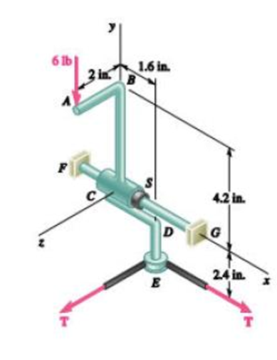
PROBLEM 4.121
The assembly shown is used to control the tension T in a tape that passes around a frictionless spool at E. Collar C is welded to rods ABC and CDE. It can rotate about shaft FG but its motion along the shaft is prevented by a washer S. For the loading shown, determine (a) the tension T in the tape, (b) the reaction at C.
Expert Solution & Answer
Want to see the full answer?
Check out a sample textbook solution
Students have asked these similar questions
A piston–cylinder device contains 50 kg of water at 250 kPa and 25°C. The cross-sectional area of the piston is 0.1 m2. Heat is now transferred to the water, causing part of it to evaporate and expand. When the volume reaches 0.26 m3, the piston reaches a linear spring whose spring constant is 100 kN/m. More heat is transferred to the water until the piston rises 20 cm more.
NOTE: This is a multi-part question. Once an answer is submitted, you will be unable to return to this part.
Determine the final pressure and temperature.
The final pressure is kPa.
The final temperature is ºC.
Find the work done during the process
A garden hose attached with a nozzle is used to fill a 20-gal bucket. The inner diameter of the hose is 1 in and it reduces to 0.53 in at the nozzle exit. The average velocity in the hose is 8 ft/s and the density of water is 62.4 lbm/ft3.
NOTE: This is a multi-part question. Once an answer is submitted, you will be unable to return to this part.
Determine the volume and mass flow rates of water through the hose.
The volume flow rate of water through the hose is ft3/s.
The mass flow rate of water through the hose is lbm/s.
The change in time?
What is the exit velocity?
A 23-ft3 rigid tank initially contains saturated refrigerant-134a vapor at 160 psia. As a result of heat transfer from the refrigerant, the pressure drops to 50 psia.
NOTE: This is a multi-part question. Once an answer is submitted, you will be unable to return to this part.
Determine the final temperature. Use data from refrigerant tables.
The final temperature is ºF.
Chapter 4 Solutions
VECTOR MECHANIC
Ch. 4.1 - Two crates, each of mass 350 kg, are placed as...Ch. 4.1 - A lever AB is hinged at C and attached to a...Ch. 4.1 - A light rod AD is supported by frictionless pegs...Ch. 4.1 - A tension of 20 N is maintained in a tape as it...Ch. 4.1 - A gardener uses a 60 N wheelbarrow to transport a...Ch. 4.1 - The gardener of Prob. 4.1 wishes to transport a...Ch. 4.1 - A 2100-lb tractor is used to lift 900 lb of grave....Ch. 4.1 - For the beam and loading shown, determine (a) the...Ch. 4.1 - A load of lumber of weight W = 25 kN is being...Ch. 4.1 - A load of lumber of weight W = 25 kN is being...
Ch. 4.1 - A hand truck is used to move a compressed-air...Ch. 4.1 - Two external shafts of a gearbox are subject to...Ch. 4.1 - Three loads are applied as shown to a light beam...Ch. 4.1 - The 10-m beam AB rests upon, but is not attached...Ch. 4.1 - The maximum allowable value of each of the...Ch. 4.1 - For the beam of Sample Prob. 4.2, determine the...Ch. 4.1 - The maximum allowable value of each of the...Ch. 4.1 - For the beam and loading shown, determine the...Ch. 4.1 - PROBLEM 4.15 The required tension in cable AB is...Ch. 4.1 - PROBLEM 4.16 Determine the maximum tension that...Ch. 4.1 - Two links AB and DE are connected by a bell crank...Ch. 4.1 - Two links AB and DE are connected by a bell crank...Ch. 4.1 - The bracket BCD is hinged at C and attached to a...Ch. 4.1 - The ladder AB, of length L and weight W, can be...Ch. 4.1 - The ladder AB, of length L and weight W, can be...Ch. 4.1 - A lever AB is hinged at C and attached to a...Ch. 4.1 - 4.23 and 4.24 For each of the plates and loadings...Ch. 4.1 - Prob. 4.24PCh. 4.1 - A rod AB, hinged at A and attached at B to cable...Ch. 4.1 - Prob. 4.26PCh. 4.1 - For the frame and loading shown, determine the...Ch. 4.1 - Determine the reactions at A and C when (a) = 0,...Ch. 4.1 - The spanner shown is used to rotate a shaft. A pin...Ch. 4.1 - The spanner shown is used to rotate a shaft. A pin...Ch. 4.1 - Neglecting friction, determine the tension in...Ch. 4.1 - Fig. P4.31 and P4.32 4.32 Neglecting friction,...Ch. 4.1 - PROBLEM 4.33 A force P of magnitude 90 lb is...Ch. 4.1 - PROBLEM 4.34 Solve Problem 4,33 for a = 6 in,...Ch. 4.1 - Prob. 4.35PCh. 4.1 - PROBLEM 4.36 A light bar AD is suspended from a...Ch. 4.1 - A 160-lb overhead garage door consists of a...Ch. 4.1 - Fig. P4.37 4.38 In Prob. 4.37, determine the...Ch. 4.1 - Prob. 4.39PCh. 4.1 - Fig. P4.39 4.40 Solve Prob. 4.39 when = 30.Ch. 4.1 - The semicircular rod ABCD is maintained in...Ch. 4.1 - Prob. 4.42PCh. 4.1 - The rig shown consists of a 1200-lb horizontal...Ch. 4.1 - Fig. P4.43 4.44 For the rig and crate of Prob....Ch. 4.1 - Prob. 4.45PCh. 4.1 - Knowing that the tension in wire BD is 1300 N,...Ch. 4.1 - Prob. 4.47PCh. 4.1 - Beam AD carries the two 40-lb loads shown. The...Ch. 4.1 - Fig. P4.48 and P4.49 4.49 For the beam and loading...Ch. 4.1 - A traffic-signal pole may be supported in the...Ch. 4.1 - A uniform rod AB with a length of l and weight of...Ch. 4.1 - Rod AD is acted upon by a vertical force P at end...Ch. 4.1 - A slender rod AB with a weigh of W is attached to...Ch. 4.1 - 4.54 and 4.55 A vertical load P is applied at end...Ch. 4.1 - 4.54 and 4.55 A vertical load P is applied at end...Ch. 4.1 - A collar B with a weight of W can move freely...Ch. 4.1 - A 400-lb weight is attached at A to the lever...Ch. 4.1 - A vertical load P is applied at end B of rod BC....Ch. 4.1 - Prob. 4.59PCh. 4.1 - A truss can be supported in the eight different...Ch. 4.2 - A 500-lb cylindrical tank, 8 ft in diameter, is to...Ch. 4.2 - Determine the reactions at A and E when =0.Ch. 4.2 - Determine (a) the value of for which the reaction...Ch. 4.2 - A 12-ft ladder, weighing 40 lb, leans against a...Ch. 4.2 - Determine the reactions at B and C when a = 30 mm.Ch. 4.2 - Determine the reactions at A and E. Fig. P4.66Ch. 4.2 - Determine the reactions at B and D when b = 60 mm....Ch. 4.2 - For the frame and loading shown, determine the...Ch. 4.2 - A 50-kg crate is attached to the trolley-beam...Ch. 4.2 - One end of rod AB rests in the corner A and the...Ch. 4.2 - For the boom and loading shown, determine (a) the...Ch. 4.2 - A 50-lb sign is supported by a pin and bracket at...Ch. 4.2 - Determine the reactions at A and D when = 30.Ch. 4.2 - Determine the reactions at A and D when = 60.Ch. 4.2 - Rod AB is supported by a pin and bracket at A and...Ch. 4.2 - Solve Prob. 4.75, assuming that the 170-N force...Ch. 4.2 - The L-shaped member ACB is supported by a pin and...Ch. 4.2 - Using the method of Sec. 4.2B, solve Prob. 4.22....Ch. 4.2 - Knowing that = 30, determine the reaction (a) at...Ch. 4.2 - Knowing that = 60, determine the reaction (a) at...Ch. 4.2 - Determine the reactions at A and B when = 50....Ch. 4.2 - Determine the reactions at A and B when = 80.Ch. 4.2 - Rod AB is bent into the shape of an arc of circle...Ch. 4.2 - A slender rod of length L is attached to collars...Ch. 4.2 - An 8-kg slender rod of length L is attached to...Ch. 4.2 - Prob. 4.86PCh. 4.2 - A slender rod BC with a length of L and weight W...Ch. 4.2 - A thin ring with a mass of 2 kg and radius r = 140...Ch. 4.2 - A slender rod with a length of L and weight W is...Ch. 4.2 - Fig. P4.89 4.90 Knowing that for the rod of Prob....Ch. 4.3 - Two tape spools are attached to an axle supported...Ch. 4.3 - Prob. 4.6FBPCh. 4.3 - A 20-kg cover for a roof opening is hinged at...Ch. 4.3 - Prob. 4.91PCh. 4.3 - Prob. 4.92PCh. 4.3 - A small winch is used to raise a 120-lb load. Find...Ch. 4.3 - Two transmission belts pass over sheaves welded to...Ch. 4.3 - A 250 400-mm plate of mass 12 kg and a...Ch. 4.3 - Prob. 4.96PCh. 4.3 - The rectangular plate shown weighs 60 lb and is...Ch. 4.3 - A load W is to be placed on the 60-lb plate of...Ch. 4.3 - Prob. 4.99PCh. 4.3 - Prob. 4.100PCh. 4.3 - PROBLEM 4.101 Two steel pipes AB and BC, each...Ch. 4.3 - PROBLEM 4.102 For the pipe assembly of Problem...Ch. 4.3 - PROBLEM 4.103 The 24-lb square plate shown is...Ch. 4.3 - PROBLEM 4.104 The table shown weighs 30 lb and has...Ch. 4.3 - PROBLEM 4.105 A 10-ft boom is acted upon by the...Ch. 4.3 - PROBLEM 4.106 The 6-m pole ABC is acted upon by a...Ch. 4.3 - PROBLEM 4.107 Solve Problem 4.106 for a = 1.5 m....Ch. 4.3 - A 3-m pole is supported by a ball-and-socket joint...Ch. 4.3 - PROBLEM 4.109 A 3-m pole is supported by a...Ch. 4.3 - PROBLEM 4.110 A 7-ft boom is held by a ball and...Ch. 4.3 - PROBLEM 4.111 A 48-in. boom is held by a...Ch. 4.3 - PROBLEM 4.112 Solve Problem 4.111, assuming that...Ch. 4.3 - PROBLEM 4.114 The bent rod ABEF is supported by...Ch. 4.3 - The bent rod ABEF is supported by bearings at C...Ch. 4.3 - The horizontal platform ABCD weighs 60 lb and...Ch. 4.3 - Prob. 4.116PCh. 4.3 - Prob. 4.117PCh. 4.3 - Solve Prob. 4.117, assuming that cable DCE is...Ch. 4.3 - PROBLEM 4.119 Solve Prob. 4.113, assuming that the...Ch. 4.3 - PROBLEM 4.120 Solve Prob. 4.115, assuming that the...Ch. 4.3 - PROBLEM 4.121 The assembly shown is used to...Ch. 4.3 - Prob. 4.122PCh. 4.3 - PROBLEM 4.123 The rigid L-shaped member ABC is...Ch. 4.3 - Solve Prob. 4.123; assuming that cable BD is...Ch. 4.3 - Prob. 4.125PCh. 4.3 - Prob. 4.126PCh. 4.3 - Prob. 4.127PCh. 4.3 - Prob. 4.128PCh. 4.3 - Frame ABCD is supported by a ball-and-socket joint...Ch. 4.3 - Prob. 4.130PCh. 4.3 - The assembly shown consists of an 80-mm rod AF...Ch. 4.3 - Prob. 4.132PCh. 4.3 - The frame ACD is supported by ball-and-socket...Ch. 4.3 - Prob. 4.134PCh. 4.3 - The 8-ft rod AB and the 6-ft rod BC are hinged at...Ch. 4.3 - Solve Prob. 4.135 when h = 10.5 ftCh. 4.3 - Prob. 4.137PCh. 4.3 - Prob. 4.138PCh. 4.3 - Prob. 4.139PCh. 4.3 - Prob. 4.140PCh. 4.3 - Prob. 4.141PCh. 4 - Prob. 4.142RPCh. 4 - 4. 143 The lever BCD is hinged at C and attached...Ch. 4 - Prob. 4.144RPCh. 4 - Neglecting friction and the radius of the pulley,...Ch. 4 - Prob. 4.146RPCh. 4 - PROBLEM 4.147 A slender rod AB, of weight W, is...Ch. 4 - PROBLEM 4.148 Determine the reactions at A and B...Ch. 4 - Prob. 4.149RPCh. 4 - PROBLEM 4.150 A 200-mm lever and a 240-mm-diameter...Ch. 4 - Prob. 4.151RPCh. 4 - Prob. 4.152RPCh. 4 - A force P is applied to a bent rod ABC, which may...
Knowledge Booster


Learn more about
Need a deep-dive on the concept behind this application? Look no further. Learn more about this topic, mechanical-engineering and related others by exploring similar questions and additional content below.Similar questions
- A 23-ft3 rigid tank initially contains saturated refrigerant-134a vapor at 160 psia. As a result of heat transfer from the refrigerant, the pressure drops to 50 psia. NOTE: This is a multi-part question. Once an answer is submitted, you will be unable to return to this part. Determine the heat transfer. The heat transfer is Btu.arrow_forwardThe shaft shown in the figure below is subjected to axial loads as illustrated. The diameters of segments AB, BC, and CD are 20mm, 25mm, and 15mm, respectively. If the modulus of elasticity of the material is 610 MPa. Determine the change of A to D lengtharrow_forwardDetermine the final pressure and temperature. The final pressure is kPa. The final temperature is ºC.arrow_forward
- Air enters the 1-m2 inlet of an aircraft engine at 100 kPa and 20°C with a velocity of 184 m/s. Determine the volume flow rate, in m3/s, at the engine’s inlet and the mass flow rate, in kg/s, at the engine’s exit. The gas constant of air is R = 0.287 kPa·m3/kg·K. The volume flow rate at the engine’s inlet m3/s. The mass flow rate at the engine’s exit is kg/s.arrow_forwardThe ventilating fan of the bathroom of a building has a volume flow rate of 33 L/s and runs continuously. If the density of air inside is 1.20 kg/m3, determine the mass of air vented out in one day. The mass of air is kg.arrow_forwardA steady-flow compressor is used to compress helium from 15 psia and 70°F at the inlet to 200 psia and 600°F at the outlet. The outlet area and velocity are 0.01 ft2 and 100 ft/s, respectively, and the inlet velocity is 53 ft/s. Determine the mass flow rate and the inlet area. The gas constant of helium is R = 2.6809 psia·ft3/lbm·R. The mass flow rate is lbm/s. The inlet area is ft2.arrow_forward
- 1. The maximum and minimum stresses as well as the shear stress seen subjected the piece in plane A-A. Assume it is a cylinder with a diameter of 12.7mm 2. Draw the Mohr circle for the stress state using software. 3. Selection of the material for the prosthesis, which must be analyzed from the point of safety and cost view.arrow_forwardMarrow_forward× Your answer is incorrect. (Manometer) Determine the angle 0 of the inclined tube shown in figure below if the pressure at A is 1 psi greater than that at B. 1ft SG=0.61 十 A Ꮎ 1ft SG=1.0 8.8 ft 0 = Hi 15.20 deg Airarrow_forward
- I don't know how to solve thisarrow_forward1. The maximum and minimum stresses as well as the shear stress seen subjected the piece in plane A-A. Assume it is a cylinder with a diameter of 12.7mm 2. Draw the Mohr circle for the stress state using software. 3. Selection of the material for the prosthesis, which must be analyzed from the point of safety and cost view.arrow_forwardFirst, define the coordinate system XY with its origin at O2 and X-axis passing through O4 asshown above, then based on the provided steps Perform coordinate transformation from XY to xy to get the trajectory of point P. Show all the steps and calcualtionsarrow_forward
arrow_back_ios
SEE MORE QUESTIONS
arrow_forward_ios
Recommended textbooks for you
 Elements Of ElectromagneticsMechanical EngineeringISBN:9780190698614Author:Sadiku, Matthew N. O.Publisher:Oxford University Press
 Mechanics of Materials (10th Edition)Mechanical EngineeringISBN:9780134319650Author:Russell C. HibbelerPublisher:PEARSON
 Thermodynamics: An Engineering ApproachMechanical EngineeringISBN:9781259822674Author:Yunus A. Cengel Dr., Michael A. BolesPublisher:McGraw-Hill Education
 Control Systems EngineeringMechanical EngineeringISBN:9781118170519Author:Norman S. NisePublisher:WILEY
 Mechanics of Materials (MindTap Course List)Mechanical EngineeringISBN:9781337093347Author:Barry J. Goodno, James M. GerePublisher:Cengage Learning
 Engineering Mechanics: StaticsMechanical EngineeringISBN:9781118807330Author:James L. Meriam, L. G. Kraige, J. N. BoltonPublisher:WILEY
Elements Of Electromagnetics
Mechanical Engineering
ISBN:9780190698614
Author:Sadiku, Matthew N. O.
Publisher:Oxford University Press
Mechanics of Materials (10th Edition)
Mechanical Engineering
ISBN:9780134319650
Author:Russell C. Hibbeler
Publisher:PEARSON
Thermodynamics: An Engineering Approach
Mechanical Engineering
ISBN:9781259822674
Author:Yunus A. Cengel Dr., Michael A. Boles
Publisher:McGraw-Hill Education
Control Systems Engineering
Mechanical Engineering
ISBN:9781118170519
Author:Norman S. Nise
Publisher:WILEY
Mechanics of Materials (MindTap Course List)
Mechanical Engineering
ISBN:9781337093347
Author:Barry J. Goodno, James M. Gere
Publisher:Cengage Learning
Engineering Mechanics: Statics
Mechanical Engineering
ISBN:9781118807330
Author:James L. Meriam, L. G. Kraige, J. N. Bolton
Publisher:WILEY
Dynamics - Lesson 1: Introduction and Constant Acceleration Equations; Author: Jeff Hanson;https://www.youtube.com/watch?v=7aMiZ3b0Ieg;License: Standard YouTube License, CC-BY