
Concept explainers
Videos
(a)
The tension on the cable.
(a)
Answer to Problem 4.117P
The tension on the cable is
Explanation of Solution
The tension in the cable
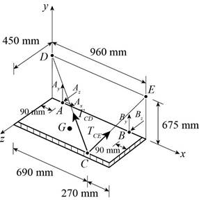
Figure 1
The position vector of the point
The position vector of the point
The position vector of the point
The vector
The tension across the cable from
Here,
Substitute
The tension across the cable from
Here,
Substitute
The weight is given as,
Here,
Substitute
The force on the point is zero. This means that the sum of the moments of the force will also be zero.
Here,
Substitute the vector values and determine the cross product.
Conclusion:
Equate the coefficients of
Therefore, the tension on the cable is
(b)
The reactions at
(b)
Answer to Problem 4.117P
The reactions at
Explanation of Solution
The free body diagram of the given arrangement is given in Figure 1.
Equate the coefficients of
Equate the coefficients of
The net force acting on the point is zero.
Here,
Substitute
Equate the coefficients of
Equate the coefficients of
Equate the coefficients of
Conclusion:
From (II) and (III) the vector
And, from (V), (VI) and (VII) the vector
Therefore, the reactions at
Want to see more full solutions like this?
Chapter 4 Solutions
Connect 1 Semester Access Card for Vector Mechanics for Engineers: Statics and Dynamics


- please show a drawing/image and explain how to properly do the question. thanksarrow_forwardFor the four-bar- linkage shown in the following figure. BC=68mm, CD=100mm, AD=120mm. Determine the range of AB to make it a crank-rocker mechanism. B Darrow_forwardall of those 4 fi 1)Draw kinematic diagram: 2)DOF: 3)type/name of mechanism 4)evolution:arrow_forward
- 7.4 Impeller viscometer The rheology of a Penicillium chrysogenum broth is examined using an impeller viscometer. The density of the cell suspension is approximately 1000 kg m³. Samples of broth are stirred under laminar conditions using a Rushton turbine of diameter 4 cm in a glass beaker of diameter 15 cm. The average shear rate generated by the impeller is greater than the stirrer speed by a factor of about 10.2. When the stirrer shaft is attached to a device for measuring torque and rotational speed, the following results are recorded. Stirrer speed (s¹) Torque (Nm) 0.185 3.57 × 10⁻⁶ 0.163 3.45 × 10⁻⁶ 0.126 3.31 x 10⁻⁶ 0.111 3.20×10⁻⁶ Can the rheology be described using a power-law model? If so, evaluate K and n.arrow_forward(read image)arrow_forward(read image) Answer Providedarrow_forward
- This is part B Part A's question and answer was find moment of inertia (Ix = 3.90×10^5) and radius of gyration (kx = 21.861) Determine the centroid ( x & y ) of the I-section, Calculate the moment of inertia of the section about itscentroidal x & y axes. How or why is this result different fromthe result of a previous problem?arrow_forwardDetermine by direct integration the moment of inertia of theshaded area of figure with respect to the y axis shownarrow_forwardConsider the feedback controlled blending system shown below, which is designed to keep theoutlet concentration constant despite potential variations in the stream 1 composition. The density of all streamsis 920 kg/m3. At the nominal steady state, the flow rates of streams 1 and 2 are 950 and 425 kg/min,respectively, the liquid level in the tank is 1.3 m, the incoming mass fractions are x1 = 0.27, x2 = 0.54. Noticethe overflow line, indicating that the liquid level remains constant (i.e. any change in total inlet flow ratetranslates immediately to the same change in the outlet flow rate). You may assume the stream 1 flowrate andthe stream 2 composition are both constant. Use minutes as the time unit throughout this problem. Identify any controlled variable(s) (CVs), manipulated variable(s) (MVs),and disturbance variable(s) (DVs) in this problem. For each, explain how you know that’show it is classified.CVs: ___________, MVs: _____________, DVs: ______________ b) Draw a block diagram…arrow_forward
- A heat transfer experiment is conducted on two identical spheres which are initially at the same temperature. The spheres are cooled by placing them in a channel. The fluid velocity in the channel is non-uniform, having a profile as shown. Which sphere cools off more rapidly? Explain. V 1arrow_forwardMy ID# 016948724 last 2 ID# 24 Last 3 ID# 724 Please help to find the correct answer for this problem using my ID# first write le line of action and then help me to find the forces {fx= , fy= mz= and for the last find the moment of inertial about the show x and y axes please show how to solve step by steparrow_forwardMy ID# 016948724 last 2 ID# 24 Last 3 ID# 724 Please help to find the correct answer for this problem using my ID# first write le line of action and then help me to find the forces and the tension {fx= , fy= mz=arrow_forward
 International Edition---engineering Mechanics: St...Mechanical EngineeringISBN:9781305501607Author:Andrew Pytel And Jaan KiusalaasPublisher:CENGAGE L