
Concept explainers
a.
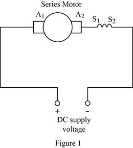
Draw the diagram of series motor.
a.
Explanation of Solution
DC motor:
A DC motor is an electrical rotary machine that is used to convert electrical power into
Series motor:
In the series motor, the field winding and armature winding are connected in series. Since the field and armature winding are in series, it should be large enough to carry the current of the armature circuit. The diagram of series motor is shown in Figure 1. The series field winding is represented as
Conclusion:
Thus, the diagram of series motor is drawn.
b.
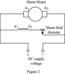
Draw the diagram of shunt motor.
b.
Explanation of Solution
Shunt motor:
In the shunt motor, the field and armature winding are in parallel connection. The rheostat is connected in series with field winding to vary the resistance of field circuit. The diagram of shunt motor is shown in Figure 2. The shunt connected field winding is represented as
Conclusion:
Thus, the diagram of shunt motor is drawn.
c.
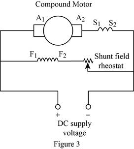
Draw the diagram of compound motor.
c.
Explanation of Solution
Compound motor:
The compound motor has both a series and shunt field winding. The diagram of compound motor is shown in Figure 3.
Conclusion:
Thus, the diagram of compound motor is drawn.
Want to see more full solutions like this?


- NO AI PLEASE WILL REJECTarrow_forwardNO AI PLEASE WILL REJECTarrow_forwardCalculate A, B, C, and D constants, sending end voltage and sending end current of a 3-phase, 50-Hz overhead transmission line 100 km long has the following constants Resistance/km/phase = 0.1, Inductive reactance/km/phase 0.20, Capacitive susceptance/km/phase = 0.04 x 10 siemen. when supplying a balanced load of 10,000 kW at 66 kV, p.f. 0-8 lagging. Use nominal T method. andarrow_forward
- Don't use ai to answer I will report you answer. Please give explanation for both correct options and incorrectarrow_forward14:00 APP Voi) 5G 鼷浴醵郯興47% atheva.cc/index/index/index.html The Most Trusted, Secure, Fast, Reliable Cryptocurrency Exchange Get started with the easiest and most secure platform to buy, sell, trade, and earn Cryptocurrency Balance:1000.00 Recharge Withdraw Message About us BTC/USDT ETH/USDT EOS/USDT 83259.00 1841.46 83259.00 +1.02% +0.08% +1.02% Operating norms Symbol B BTC/USDT Latest price 24hFluctuation 83259.00 +1.02% ETH/USDT 1841.46 +0.08% B BTC/USD illı 83259.00 +1.02% Home Markets Trade Record Mine О <arrow_forwardPastner Brands is a calendar-year firm with operations in several countries. As part of its executive compensation plan, at January 1, 2024, the company issued 480,000 executive stock options permitting executives to buy 480,000 shares of Pastner stock for $38 per share. One-fourth of the options vest in each of the next four years beginning at December 31, 2024 (graded vesting). Pastner elects to separate the total award into four groups (or tranches) according to the year in which they vest and measures the compensation cost for each vesting date as a separate award. The fair value of each tranche is estimated at January 1, 2024, as follows: Vesting Date Amount Fair Value Vesting per Option: December 31, 2024 25% $ 3.90 December 31, 2025 25% $ 4.40 25% $ 4.90 25% $ 5.40 December 31, 2026 December 31, 2027 Required: 1. Determine the compensation expense related to the options to be recorded each year 2024-2027, assuming Pastner allocates the compensation cost for each of the four…arrow_forward
- JOB UPDATE Apply on- Jobswood.com OR Search "Jobswood.com" on Google COMPANY JOB PROFILE JOB LOCATION WEB ENGINEER GOOGLE MULTIPLE CITIES (FRESHERS) AMAZON SOFTWARE DEV ENGG MULTIPLE CITIES COGNIZANT SYSTEMS ENGINEER CHENNAI ZENSAR FRONTEND DEVELOPER BENGALURU ORACLE AUTOMATION ENGINEER BENGALURU DIGITAL OCEAN SUPPORT ENGINEER HYDERABAD IBM APPLICATION DEVELOPER HYDERABAD INDIAMART WORK FROM HOME MULTIPLE CITIES AMAZON RECRUITER HYDERABAD GE HEALTHCARE TRAINEE ENGINEER BENGALURUarrow_forwardJOB UPDATE Apply on Vinkjobs.com OR Search "VinkJobs.com" on Google Company Name Job Profile Job Location CISCO Software Engineer Bengaluru Accenture Associate (Freshers) Chennai Trellix Developer Bengaluru Verizon SDET Bengaluru Allerin Test Engineer Mumbai Sutherland SQL/.Net Developer Chennai Bottomline DevOps Engineer Multiple Cities IQVIA HRIS Specialist Bengaluru BYJU's Associate Multiple Cities Spring Works Executive WFH (Remote)arrow_forwardDon't use ai to answer I will report you answerarrow_forward

 Delmar's Standard Textbook Of ElectricityElectrical EngineeringISBN:9781337900348Author:Stephen L. HermanPublisher:Cengage Learning