
Mechanics of Materials, Student Value Edition (10th Edition)
10th Edition
ISBN: 9780134321189
Author: Russell C. Hibbeler
Publisher: PEARSON
expand_more
expand_more
format_list_bulleted
Videos
Textbook Question
Chapter 4.2, Problem 4.19P
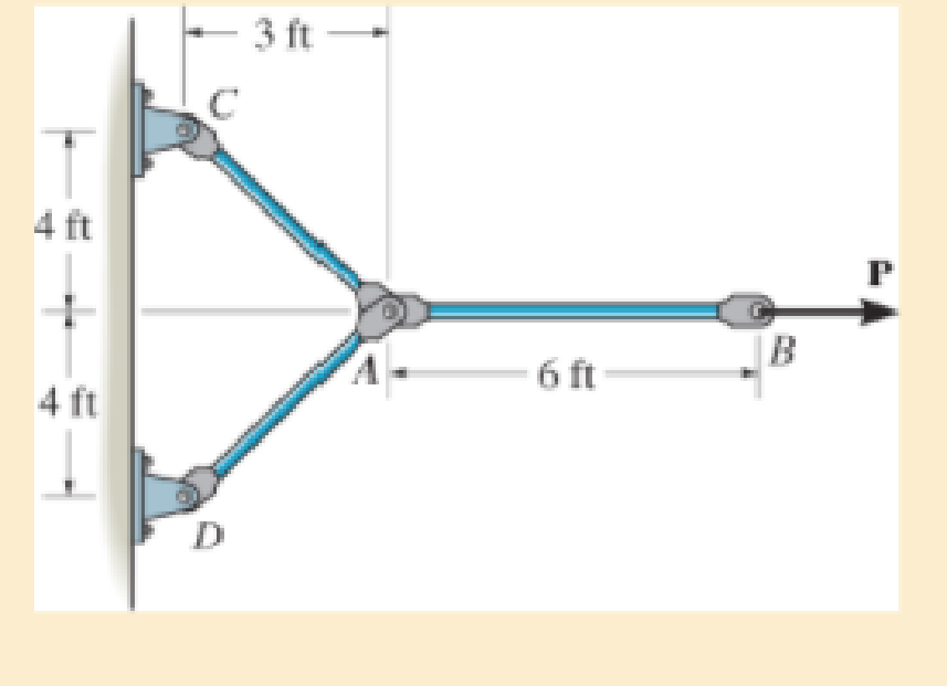
The linkage is made of three pin connected A992 steel members, each having a diameter of
Expert Solution & Answer
Want to see the full answer?
Check out a sample textbook solution
Students have asked these similar questions
A 2D incompressible flow has velocitycomponents u= X^2 - 2y^2 and v=aX^b y^c
,where a, b, and c are numbers.
Find the values of a, b, and c
Find the stream function
Please can you assist with the attached question please?
(a) Find a second-order homogeneous linear ODE for which the given functions are
solutions. (b) Show linear independence by the Wronskian. (c) Solve the initial value
problem.
a. cos(5x), sin(5x), y(0) = 3, y'(0) = −5
b. e-2.5x cos(0.3x), e-2.5x sin(0.3x), y(0) = 3, y'(0) = -7.5
Chapter 4 Solutions
Mechanics of Materials, Student Value Edition (10th Edition)
Ch. 4.2 - In each case, determine the internal normal force...Ch. 4.2 - Determine the internal normal force between...Ch. 4.2 - The post weighs 8kN/m. Determine the internal...Ch. 4.2 - The rod is subjected to an external axial force of...Ch. 4.2 - The rigid beam supports the load of 60 kN....Ch. 4.2 - The 20-mm-diameter A-36 steel rod is subjected to...Ch. 4.2 - Segments AB and CD of the assembly are solid...Ch. 4.2 - The 30-mm-diameter A992 steel rod is subjected to...Ch. 4.2 - If the 20-mm-diameter rod is made of A-36 steel...Ch. 4.2 - The 20-mm-diameter 2014-T6 aluminum rod is...
Ch. 4.2 - The 20-mm-diameter 2014-T6 aluminum rod is...Ch. 4.2 - The A992 steel rod is subjected to the loading...Ch. 4.2 - The copper shaft is subjected to the axial loads...Ch. 4.2 - The composite shaft, consisting of aluminum,...Ch. 4.2 - The composite shaft, consisting of aluminum,...Ch. 4.2 - The 2014-T6 aluminium rod has a diameter of 30 mm...Ch. 4.2 - The A-36 steel drill shaft of an oil well extends...Ch. 4.2 - The truss is made of three A-36 steel members,...Ch. 4.2 - The truss is made of three A-36 steel members,...Ch. 4.2 - The assembly consists of two 10-mm diameter red...Ch. 4.2 - The assembly consists of two 10-mm diameter red...Ch. 4.2 - The load is supported by the four 304 stainless...Ch. 4.2 - The load is supported by the four 304 stainless...Ch. 4.2 - The rigid bar is supported by the pin-connected...Ch. 4.2 - The post is made of Douglas fir and has a diameter...Ch. 4.2 - The post is made of Douglas fir and has a diameter...Ch. 4.2 - The coupling rod is subjected to a force of 5 kip....Ch. 4.2 - The pipe is stuck in the ground so that when it is...Ch. 4.2 - The is made of three pin-connected A992 steel...Ch. 4.2 - The linkage is made of three pin connected A992...Ch. 4.2 - The assembly consists of three titanium...Ch. 4.2 - The rigid beam is supported at its ends by two...Ch. 4.2 - The rigid beam is supported at its ends by two...Ch. 4.2 - The steel bar has the original dimensions shown in...Ch. 4.2 - Determine the relative displacement of one end of...Ch. 4.2 - The assembly consists of two rigid bars that are...Ch. 4.2 - The truss consists of three members, each made...Ch. 4.2 - Solve Prob. 426 when the load P acts vertically...Ch. 4.2 - The observation cage C has a weight of 250 kip and...Ch. 4.2 - The steel bar has the original dimensions shown in...Ch. 4.2 - The ball is truncated at its ends and is used to...Ch. 4.5 - The column is constructed from high-strength...Ch. 4.5 - The column is constructed from high-strength...Ch. 4.5 - The A-36 steel pipe has a 6061-T6 aluminum core....Ch. 4.5 - If column AB is made from high strength precast...Ch. 4.5 - If column AB is made from high strength precast...Ch. 4.5 - Determine the support reactions at the rigid...Ch. 4.5 - If the supports at A and C are flexible and have a...Ch. 4.5 - The load of 2000 lb is to be supported by the two...Ch. 4.5 - The load of 2000 lb is to be supported by the two...Ch. 4.5 - The A-36 steel pipe has an outer radius of 20 mm...Ch. 4.5 - The 10-mm-diameter steel bolt is surrounded by a...Ch. 4.5 - The 10-mm-diameter steel bolt is surrounded by a...Ch. 4.5 - The assembly consists of two red brass C83400...Ch. 4.5 - The rigid beam is supported by the three suspender...Ch. 4.5 - The bolt AB has a diameter of 20 mm and passes...Ch. 4.5 - If the gap between C and the rigid wall at D is...Ch. 4.5 - The support consists of a solid red brass C83400...Ch. 4.5 - If there are n fibers, each having a...Ch. 4.5 - The rigid bar is pinned at A and supported by two...Ch. 4.5 - The rigid bar is pinned at A and supported by two...Ch. 4.5 - The rigid bar is pinned at A and supported by two...Ch. 4.5 - The rigid bar is pinned at A and supported by two...Ch. 4.5 - The 2014-T6 aluminum rod AC is reinforced with the...Ch. 4.5 - The 2014-T6 aluminum rod AC is reinforced with the...Ch. 4.5 - The three suspender bars are made of A992 steel...Ch. 4.5 - The three A-36 steel wires each have a diameter of...Ch. 4.5 - The A-36 steel wires AB and AD each have a...Ch. 4.5 - The post is made from 6061-T6 aluminum and has a...Ch. 4.5 - The post is made from 6061-T6 aluminum and has a...Ch. 4.5 - The bracket is held to the wall using three A-36...Ch. 4.5 - The bracket is held to the wall using three A-36...Ch. 4.5 - If each of the posts has an unloaded length of 1 m...Ch. 4.5 - The rigid bar is supported by the two short white...Ch. 4.5 - The assembly consists of two posts AB and CD each...Ch. 4.5 - The assembly consists of two posts AB and CD each...Ch. 4.5 - The assembly consists of two posts AB and CD each...Ch. 4.5 - The wheel is subjected to a force of 18 kN from...Ch. 4.6 - The C83400-red-brass rod AB and 2014-T6- aluminum...Ch. 4.6 - The assembly has the diameters and material...Ch. 4.6 - The rod is made of A992 steel and has a diameter...Ch. 4.6 - The two cylindrical rod segments are fixed to the...Ch. 4.6 - The two cylindrical rod segments are fixed to the...Ch. 4.6 - The pipe is made of A992 steel and is connected to...Ch. 4.6 - The bronze C86100 pipe has an inner radius of 0.5...Ch. 4.6 - The 40-ft-long A-36 steel rails on a train track...Ch. 4.6 - The device is used to measure a change in...Ch. 4.6 - The bar has a cross-sectional area A, length L,...Ch. 4.6 - When the temperature is at 30C, the A-36 steel...Ch. 4.6 - When the temperature is at 30C, the A-36 steel...Ch. 4.6 - When the temperature is at 30C, the A-36 steel...Ch. 4.6 - The 50-mm-diameter cylinder is made from Am...Ch. 4.6 - The 50-mm-diameter cylinder is made from Am...Ch. 4.6 - The wires AB and AC are made of steel, and wire AD...Ch. 4.6 - The cylinder CD of the assembly is heated from T1...Ch. 4.6 - The cylinder CD of the assembly is heated from T1=...Ch. 4.6 - The metal strap has a thickness t and width w and...Ch. 4.9 - Determine the maximum normal stress developed in...Ch. 4.9 - If the allowable normal stress for the bar is...Ch. 4.9 - The steel bar has the dimensions shown. Determine...Ch. 4.9 - The A-36 steel plate has a thickness of 12 mm. If...Ch. 4.9 - Determine the maximum axial force P that can be...Ch. 4.9 - Determine the maximum normal stress developed in...Ch. 4.9 - The member is to be made from a steel plate that...Ch. 4.9 - The resulting stress distribution along section AB...Ch. 4.9 - The resulting stress distribution along section AB...Ch. 4.9 - Prob. 4.96PCh. 4.9 - The weight is suspended from steel and aluminum...Ch. 4.9 - The bar has a cross-sectional area of 0.5 in2 and...Ch. 4.9 - The distributed loading is applied to the rigid...Ch. 4.9 - The distributed loading is applied to the rigid...Ch. 4.9 - The rigid lever arm is supported by two A-36 steel...Ch. 4.9 - The rigid lever arm is supported by two A-36 steel...Ch. 4.9 - The 300-kip weight is slowly set on the top of a...Ch. 4.9 - The rigid beam is supported by three 25-mm...Ch. 4.9 - The rigid beam is supported by three 25-mm...Ch. 4.9 - The rigid beam is supported by the three posts A,...Ch. 4.9 - The rigid beam is supported by the three posts A,...Ch. 4.9 - The bar having a diameter of 2 in. is fixed...Ch. 4.9 - Determine the elongation of the bar in Prob.4108...Ch. 4.9 - The rigid beam is supported by three A-36 steel...Ch. 4 - The assembly consists of two A992 steel bolts AB...Ch. 4 - The assembly shown consists of two A992 steel...Ch. 4 - The rods each have the same 25-mm diameter and...Ch. 4 - Two A992 steel pipes, each having a...Ch. 4 - The force P is applied to the bar, which is made...Ch. 4 - The 2014-T6 aluminum rod has a diameter of 0.5 in....Ch. 4 - The 2014-T6 aluminum rod has a diameter of 0.5 in....Ch. 4 - The rigid link is supported by a pin at A and two...Ch. 4 - The joint is made from three A992 steel plates...
Knowledge Booster


Learn more about
Need a deep-dive on the concept behind this application? Look no further. Learn more about this topic, mechanical-engineering and related others by exploring similar questions and additional content below.Similar questions
- Solve the IVP. a. y" 16y 17e* ; = y(0) = 6, y'(0) = -2 b. (D² + 41)y = sin(t) + ½ sin(3t) + sin(t) ; y(0) = 0, y'(0) : = 35 31arrow_forwardFind the general solution. a. y' 5y = 3ex - 2x + 1 - b. y" +4y' + 4y = e¯*cos(x) c. (D² + I)y = cos(wt), w² # 1arrow_forwardhandwritten solutions, please!!arrow_forward
- > Homework 4 - Spring 2025.pdf Spring 2025.pdf k 4 - Spring 2025.pdf (447 KB) Due: Thursday, February 27 Page 1 > of 2 ZOOM 1. A simply supported shaft is shown in Figure 1 with wo = 25 N/cm and M = 20 N cm. Use singularity functions to determine the reactions at the supports. Assume EI = 1000 kN cm². M Wo 0 10 20 30 40 50 60 70 80 90 100 110 cm Figure 1 - Problem 1 2. A support hook was formed from a rectangular bar. Find the stresses at the inner and outer surfaces at sections just above and just below O-B. 210 mmarrow_forwardA distillation column with a total condenser and a partial reboiler is separating ethanol andwater at 1.0 atm. Feed is 0.32 mol fraction ethanol and it enters as a saturated liquid at 100mol/s on the optimum plate. The distillate product is a saturated liquid with 80 mol% ethanol.The condenser removes 5615 kW. The bottoms product is 0.05 mol fraction ethanol. AssumeCMO is valid.(a) Find the number of equilibrium stages for this separation. [6 + PR](b) Find how much larger the actual reflux ratio, R, used is than Rmin, i.e. R/Rmin. [3]Note: the heats of vaporization of ethanol and water are λe = 38.58 and λw = 40.645 arrow_forwardWe have a feed that is a binary mixture of methanol and water (60.0 mol% methanol) that issent to a system of two flash drums hooked together. The vapor from the first drum is cooled,which partially condenses the vapor, and then is fed to the second flash drum. Both drumsoperate at 1.0 atm and are adiabatic. The feed to the first drum is 1000 kmol/hr. We desire aliquid product from the first drum that is 35.0 mol% methanol. The second drum operates at afraction vaporized of (V/F)2 = 0.25.(a) Find the liquid flow rate leaving the first flash drum, L1 (kmol/hr). [286 kmol/hr](b) Find the vapor composition leaving the second flash drum, y2. [0.85]arrow_forward
- = The steel curved bar shown has rectangular cross-section with a radial height h = 6 mm and thickness b = 4mm. The radius of the centroidal axis is R = 80 mm. A force P = 10 N is applied as shown. Assume the steel modulus of 207,000 MPa and G = 79.3(103) MPa, repectively. elasticity and shear modulus E = Find the vertical deflection at point B. Use Castigliano's method for a curved flexural member and since R/h > 10, neglect the effect of shear and axial load, thereby assuming that deflection is due to merely the bending moment. Note the inner and outer radii of the curves bar are: r = 80 + ½ (6) = 83 mm, r₁ = 80 − ½ (6) = 77 mm 2 2 Sπ/2 sin² 0 d = √π/² cos² 0 d0 = Π 0 4 大 C R B Parrow_forwardThe steel eyebolt shown in the figure is loaded with a force F = 75 lb. The eyebolt is formed from round wire of diameter d = 0.25 in to a radius R₁ = 0.50 in in the eye and at the shank. Estimate the stresses at the inner and outer surfaces at section A-A. Notice at the section A-A: r₁ = 0.5 in, ro = 0.75 in rc = 0.5 + 0.125 = 0.625 in Ri 200 F FAarrow_forwardI have the fallowing question and solution from a reeds naval arc book. Im just confused as to where this answer came from and the formulas used. Wondering if i could have this answer/ solution broken down and explained in detail. A ship of 7000 tonne displacement has a waterplane areaof 1500 m2. In passing from sea water into river water of1005 kg/m3 there is an increase in draught of 10 cm. Find the Idensity of the sea water. picture of the "answer" is attachedarrow_forward
- Problem A2 long steel tube has a rectangular cross-section with outer dimensions of 20 x 20 mm and a uniform wall thickness of 2. The tube is twisted along its length with torque, T. The tube material is 1045 CD steel with shear yield strength of S,, =315 MPa. Assume shear modulus, G = 79.3GPa. (a) Estimate the maximum torque that can be applied without yielding (b) Estimate the torque required to produce 5 degrees total angle of twist over the length of the tube. (c) What is the maximum torque that can be applied without yielding, if a solid rectangular shaft with dimensions of 20 x 20 is used? You may use the exact solution.arrow_forwardA simply supported beam is loaded as shown. Considering symmetry, the reactions at supports A and B are R₁ = R₂ = wa 2 Using the singularity method, determine the shear force V along the length of the beam as a function of distance x from the support A. A B Ir. 2a За W C R₁₂ x 2. Using the singularity method, determine the bending M along the length of the beam as a function of distance x, from the support A. 3. Using the singularity method, determine the beam slope and deflection along the length of the beam as a function of the distance x, from the support A. Assume the material modulus of elasticity, E and the moment of inertia of the beam cross-section, I are given.arrow_forwardA steel tube, 2 m long, has a rectangular cross-section with outer dimensions of 20 × 30 mm and a uniform wall thickness of 1 mm. The tube is twisted along its length with torque, T. The tube material is 1018 CD steel with shear yield strength of Ssy =185 MPa. Assume shear modulus, G = 79.3GPa. (a) Estimate the maximum torque that can be applied without yielding.- (b) Estimate the torque required to produce 3 degrees total angle of twist over the length of the tube. (c) What is the maximum torque that can be applied without yielding, if a solid rectangular shaft with dimensions of 20 x 30 mm is used? You may use the exact solution:arrow_forward
arrow_back_ios
SEE MORE QUESTIONS
arrow_forward_ios
Recommended textbooks for you
 International Edition---engineering Mechanics: St...Mechanical EngineeringISBN:9781305501607Author:Andrew Pytel And Jaan KiusalaasPublisher:CENGAGE L
International Edition---engineering Mechanics: St...
Mechanical Engineering
ISBN:9781305501607
Author:Andrew Pytel And Jaan Kiusalaas
Publisher:CENGAGE L
Mod-01 Lec-16 Basics of Instrumentation; Author: nptelhrd;https://www.youtube.com/watch?v=qbKnW42ZM5c;License: Standard YouTube License, CC-BY