
Electric Circuits (10th Edition)
10th Edition
ISBN: 9780133760033
Author: James W. Nilsson, Susan Riedel
Publisher: PEARSON
expand_more
expand_more
format_list_bulleted
Concept explainers
Videos
Textbook Question
Chapter 4.2, Problem 1AP
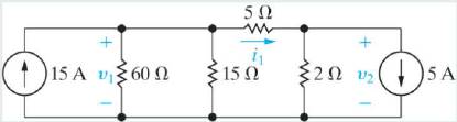
a) For the circuit shown, use the node-voltage method to find v1, v2, and i1.
b) How much power is delivered to the circuit by the 15 A source?
c) Repeat (b) for the 5 A source.
Expert Solution & Answer

Learn your wayIncludes step-by-step video

schedule06:29
Students have asked these similar questions
Q1/Sketch the root locus for the system shown in Figure 1 and find the following:
a. The exact point and gain where the locus crosses the jo-axis b. The breakaway point
on the real axis c. The range of K within which the system is stable d. Angles of
departure and arrival
R(s) +
K(s²-4s +20)
C(s)
(s+2)(s + 4)
Exam2
Subject: (Numerical Analysis)
Class: Third
Date: 27/4/2025
Time: 60 minutes
Q1. For what values of k does this system of equations has no solution? (use Gauss-Jordan eliminations)
kx + y + z = 1
x+ky + z = 1
x+y+kz=1
Consider the Difference equation of a causal Linear time-invariant (LTI) system given
by: (y(n) - 1.5y(n - 1) + 0.5y(n = 2) = x(n)
a) Implement the difference equation model of this system.
b) Find the system transfer function H(z).
c) For an input x(n) = 8(n), determine the output response y(n).
d) Verify the initial value theorem y(0) with part (c).
Chapter 4 Solutions
Electric Circuits (10th Edition)
Ch. 4.2 - a) For the circuit shown, use the node-voltage...Ch. 4.2 - Use the node-voltage method to find v in the...Ch. 4.3 - Use the node-voltage method to find the power...Ch. 4.4 - Use the node-voltage method to find vo in the...Ch. 4.4 - Use the node-voltage method to find v in the...Ch. 4.4 - Use the node-voltage method to find v1 in the...Ch. 4.5 - Use the mesh-current method to find (a) the power...Ch. 4.6 - Determine the number of mesh-current equations...Ch. 4.6 - Use the mesh-current method to find vo in the...Ch. 4.7 - Use the mesh-current method to find the power...
Ch. 4.7 - Use the mesh-current method to find the mesh...Ch. 4.7 - Use the mesh-current method to find the power...Ch. 4.8 - Find the power delivered by the 2 A current source...Ch. 4.8 - Find the power delivered by the 4 A current source...Ch. 4.9 - Use a series of source transformations to find the...Ch. 4.10 - Find the Thévenin equivalent circuit with respect...Ch. 4.10 - Prob. 17APCh. 4.10 - Prob. 18APCh. 4.11 - Find the Thévenin equivalent circuit with respect...Ch. 4.11 - Find the Thévenin equivalent circuit with respect...Ch. 4.12 - Find the value of R that enables the circuit shown...Ch. 4.12 - Assume that the circuit in Assessment Problem 4.21...Ch. 4 - For the circuit shown in Fig. P4.1, state the...Ch. 4 - If only the essential nodes and branches are...Ch. 4 - Assume the voltage vs in the circuit in Fig. P4.3...Ch. 4 - A current leaving a node is defined as...Ch. 4 - How many separate parts does the circuit in Fig....Ch. 4 - Use the node-voltage method to find vo in the...Ch. 4 - Find the power developed by the 40 mA current...Ch. 4 - A 50 Ω resistor is connected in series with the 40...Ch. 4 - Use the node-voltage method to find how much power...Ch. 4 - Use the node-voltage method to show that the...Ch. 4 - Use the node-voltage method to find the branch...Ch. 4 - Use the node-voltage method to find v1 and v2 in...Ch. 4 - Use the node-voltage method to find v1 and v2 in...Ch. 4 - Use the node-voltage method to find v1, v2, and v3...Ch. 4 - The circuit shown in Fig. P4.14 is a dc model of a...Ch. 4 - Use the node-voltage method to find the total...Ch. 4 - Use the node-voltage method to find vo in the...Ch. 4 - Use the node-voltage method to calculate the power...Ch. 4 - Use the node-voltage method to find the total...Ch. 4 - Use the node voltage method to find vo for the...Ch. 4 - Find the node voltages v1, v2, and v3 in the...Ch. 4 - Use the node-voltage method to find υ0 and the...Ch. 4 - Use the node-voltage method to find the value of...Ch. 4 - Use the node-voltage method to find io in the...Ch. 4 - Use the node-voltage method to find the power...Ch. 4 - Use the node-voltage method to find vo in the...Ch. 4 - Use the node-voltage method to find the branch...Ch. 4 - Use the node-voltage method to find the value of...Ch. 4 - Assume you are a project engineer and one of your...Ch. 4 - Use the node-voltage method to find the power...Ch. 4 - Show that when Eqs. 4.13, 4.14, and 4.16 are...Ch. 4 - Use the mesh-current method to find the branch...Ch. 4 - Solve Problem 4.11 using the mesh-current...Ch. 4 - Solve Problem 4.14 using the mesh-current...Ch. 4 - Solve Problem 4.26 using the mesh-current...Ch. 4 - Use the mesh-current method to find the total...Ch. 4 - Solve Problem 4.25 using the mesh-current...Ch. 4 - Solve Problem 4.17 using the mesh-current...Ch. 4 - Use the mesh-current method to find the power...Ch. 4 - Use the mesh-current method to find the power...Ch. 4 - Use the mesh-current method to find υ0 in the...Ch. 4 - Use mesh-current method to find the power...Ch. 4 -
Use the mesh-current method to solve for iΔ in...Ch. 4 - Solve Problem 4.10 using the mesh-current...Ch. 4 - Solve Problem 4.21 using the mesh-current...Ch. 4 - Use the mesh-current method to find the total...Ch. 4 - Use the mesh-current method to find how much power...Ch. 4 - Use the mesh-current method to determine which...Ch. 4 - Use the mesh-current method to find the total...Ch. 4 - Prob. 50PCh. 4 - Solve Problem 4.23 using the mesh-current...Ch. 4 - Use the mesh-current method to find the branch...Ch. 4 - Find the branch currents ia − ie for the circuit...Ch. 4 - Assume you have been asked to find the power...Ch. 4 - A 4 kΩ resistor is placed in parallel with the 10...Ch. 4 - Would you use the node-voltage or mesh- current...Ch. 4 - Prob. 57PCh. 4 - The variable de voltage source in the circuit in...Ch. 4 - Make a series of source transformations to find...Ch. 4 - Prob. 60PCh. 4 - Use source transformations to find the current io...Ch. 4 - Use a series of source transformations to find i0...Ch. 4 - Use source transformations to find vo in the...Ch. 4 - Prob. 64PCh. 4 - Find the Norton equivalent with respect to the...Ch. 4 - Prob. 66PCh. 4 - Find the Thévenin equivalent with respect to the...Ch. 4 - Prob. 68PCh. 4 - A Thévenin equivalent can also be determined from...Ch. 4 - Prob. 70PCh. 4 - Prob. 71PCh. 4 - Prob. 72PCh. 4 - The Wheatstone bridge in the circuit shown in Fig....Ch. 4 - Prob. 74PCh. 4 - Find the Norton equivalent with respect to the...Ch. 4 - Prob. 76PCh. 4 - Prob. 77PCh. 4 - Find the Thévenin equivalent with respect to the...Ch. 4 - Find the Thévenin equivalent with respect to the...Ch. 4 - Prob. 80PCh. 4 - Find the Norton equivalent with respect to the...Ch. 4 - The variable resistor in the circuit in Fig. P4.82...Ch. 4 - Prob. 83PCh. 4 - a) Calculate the power delivered for each value of...Ch. 4 - Find the value of the variable resistor Ro in the...Ch. 4 - A variable resistor R0 is connected across the...Ch. 4 - The variable resistor (R0) in the circuit in Fig....Ch. 4 - The variable resistor in the circuit in Fig. P4.91...Ch. 4 - The variable resistor (RL) in the circuit in Fig....Ch. 4 - The variable resistor (RO) in the circuit in Fig....Ch. 4 - In the circuit in Fig. P4.92, before the 5 mA...Ch. 4 - Use the principle of superposition to find the...Ch. 4 -
Use superposition to solve for and υ0 in the...Ch. 4 - Prob. 95PCh. 4 - Use the principle of superposition to find the...Ch. 4 - Prob. 97PCh. 4 - Use the principle of superposition to find the...Ch. 4 - Assume your supervisor has asked you to determine...Ch. 4 - Prob. 100PCh. 4 - Prob. 101PCh. 4 - Prob. 102PCh. 4 - Laboratory measurements or a dc voltage source...Ch. 4 - Prob. 104PCh. 4 - Prob. 105PCh. 4 - Repeat Problem 4.105 if Ig2 increases to 17 A and...Ch. 4 - Prob. 107PCh. 4 - Use the results given in Table 4.2 to predict the...
Additional Engineering Textbook Solutions
Find more solutions based on key concepts
Porter’s competitive forces model: The model is used to provide a general view about the firms, the competitors...
Management Information Systems: Managing The Digital Firm (16th Edition)
What is the purpose of the oxygen in oxygen arc cutting?
Degarmo's Materials And Processes In Manufacturing
Define the three types of recursive binary relationships, and give an example of each, other than the ones show...
Database Concepts (8th Edition)
Describe two properties that each candidate key must satisfy.
Modern Database Management
Random Number File Reader This exercise assumes you have completed Programming Exercise 7, Random Number File W...
Starting Out with Python (4th Edition)
Suppose the following bit patterns represent values stored in twos complement notation. Find the twos complemen...
Computer Science: An Overview (13th Edition) (What's New in Computer Science)
Knowledge Booster


Learn more about
Need a deep-dive on the concept behind this application? Look no further. Learn more about this topic, electrical-engineering and related others by exploring similar questions and additional content below.Similar questions
- Q5B. Find the type of the controller in the following figures and use real values to find the transfer function of three of them[ Hint Pi,Pd and Lead,lag are found so put the controller with its corresponding compensator]. R₁ R₂ Rz HE C2 RA HE R₁ R2 RA とarrow_forwardQ1// Sketch the root locus for the unity feedback system. Where G(s)=)= K S3+252 +25 and find the following a. Sketch the asymptotes b. The exact point and gain where the locus crosses the jo-axis c. The breakaway point on the real axis d. The range of K within which the system is stable e. Angles of departure and arrival.arrow_forwardDetermine X(w) for the given function shown in Figure (1) by applying the differentiation property of the Fourier Transform. Figure (1) -1 x(t)arrow_forward
- Can you solve a question with a drawing Determine X(w) for the given function shown in Figure (1) by applying the differentiation property of the Fourier Transform. Figure (1) -1 x(t)arrow_forwardAn inductor has a current flow of 3 A when connected to a 240 V, 60 Hz power line. The inductor has a wire resistance of 15 Find the Q of the inductorarrow_forwardصورة من s94850121arrow_forward
- The joint density function of two continuous random variables X and Yis: p(x, y) = {Keós (x + y) Find (i) the constant K 0 2 0arrow_forwardShow all the steps please, Solve for the current through R2 if E2 is replaced by a current source of 10mA using superposition theorem. R5=470Ω R2=1000Ω R6=820Ωarrow_forwardPlease solve it by explaining the steps. I am trying to prepare for my exam tomorrow, so any tips and tricks to solve similar problems are highly appreciated. Plus, this is a past exam I am using to prepare.arrow_forwardPlease solve it by explaining the steps. I am trying to prepare for my exam today, so any tips and tricks to solve similar problems are highly appreciated. Plus, this is a past exam I am using to prepare.arrow_forwardIf C is the circle |z|=4 evaluate f f (z)dz for each of the following functions using residue. 1 f(z) = z(z²+6z+4)arrow_forwardIf C is the circle |z|=4 evaluate ff(z)dz for each of the following functions using residue. f(z) z(z²+6z+4)arrow_forwardarrow_back_iosSEE MORE QUESTIONSarrow_forward_ios
Recommended textbooks for you
 Introductory Circuit Analysis (13th Edition)Electrical EngineeringISBN:9780133923605Author:Robert L. BoylestadPublisher:PEARSON
 Delmar's Standard Textbook Of ElectricityElectrical EngineeringISBN:9781337900348Author:Stephen L. HermanPublisher:Cengage Learning
 Programmable Logic ControllersElectrical EngineeringISBN:9780073373843Author:Frank D. PetruzellaPublisher:McGraw-Hill Education
 Fundamentals of Electric CircuitsElectrical EngineeringISBN:9780078028229Author:Charles K Alexander, Matthew SadikuPublisher:McGraw-Hill Education
 Electric Circuits. (11th Edition)Electrical EngineeringISBN:9780134746968Author:James W. Nilsson, Susan RiedelPublisher:PEARSON
 Engineering ElectromagneticsElectrical EngineeringISBN:9780078028151Author:Hayt, William H. (william Hart), Jr, BUCK, John A.Publisher:Mcgraw-hill Education,
Introductory Circuit Analysis (13th Edition)
Electrical Engineering
ISBN:9780133923605
Author:Robert L. Boylestad
Publisher:PEARSON
Delmar's Standard Textbook Of Electricity
Electrical Engineering
ISBN:9781337900348
Author:Stephen L. Herman
Publisher:Cengage Learning
Programmable Logic Controllers
Electrical Engineering
ISBN:9780073373843
Author:Frank D. Petruzella
Publisher:McGraw-Hill Education
Fundamentals of Electric Circuits
Electrical Engineering
ISBN:9780078028229
Author:Charles K Alexander, Matthew Sadiku
Publisher:McGraw-Hill Education
Electric Circuits. (11th Edition)
Electrical Engineering
ISBN:9780134746968
Author:James W. Nilsson, Susan Riedel
Publisher:PEARSON
Engineering Electromagnetics
Electrical Engineering
ISBN:9780078028151
Author:Hayt, William H. (william Hart), Jr, BUCK, John A.
Publisher:Mcgraw-hill Education,
Nodal Analysis for Circuits Explained; Author: Engineer4Free;https://www.youtube.com/watch?v=f-sbANgw4fo;License: Standard Youtube License