
VECTOR MECH...,STAT.+DYN.(LL)-W/ACCESS
12th Edition
ISBN: 9781260265453
Author: BEER
Publisher: MCG
expand_more
expand_more
format_list_bulleted
Concept explainers
Videos
Textbook Question
Chapter 4.1, Problem 4.49P
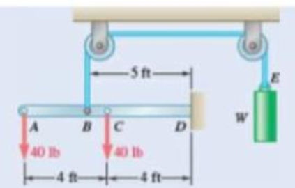
Fig. P4.48 and P4.49
4.49 For the beam and loading shown, determine the range of value W for which the magnitude of the couple at D does not exceed lb.ft.
Expert Solution & Answer
Want to see the full answer?
Check out a sample textbook solution
Students have asked these similar questions
Problem 9.5
9.5 A 1080-kg car is parked on a sloped street. The figure shows its wheels and the position of
its center of mass. The street is icy, and as a result the coefficient of static friction between
the car's tires and the street surface is μs = 0.2. Determine the steepest slope (in degrees
relative to the horizontal) at which the car could remain in equilibrium if
a. the brakes are applied to both its front and rear wheels;
b. the brakes are applied to the front (lower) wheels only.
Problem 9.5
1380 mm
532 mm
2370 mm
Can someone explain please with conversions
Correct Answer is written below. Detailed and complete fbd only please. I will upvote, thank you.
1: The assembly shown is composed of a rigid plank ABC, supported by hinge at A, spring at B and cable at C.The cable is attached to a frictionless pulley at D and rigidly supported at E. The cable is made of steel with E = 200,000MPa and cross-sectional area of 500 mm2. The details of pulley at D is shown. The pulley is supported by a pin, passingthough the pulley and attached to both cheeks. Note that E is directly above B.Given: H = 3 m; L1 = 2 m; L2 = 4 m; w = 12 kN/m; x:y = 3:4Spring Parameters:Wire diameter = 30 mmMean Radius = 90 mmNumber of turns = 12Modulus of Rigidity = 80 GPaAllowable stresses:Allowable shear stress of Pin at D = 85 MPaAllowable normal stress of cheek at D = 90MPaAllowable bearing stress of cheek at D = 110MPa1. Calculate the reaction of spring Band tension in cable at C.2. Calculate the vertical displacementat C and the required diameter ofpin at D.3.…
Chapter 4 Solutions
VECTOR MECH...,STAT.+DYN.(LL)-W/ACCESS
Ch. 4.1 - Two crates, each of mass 350 kg, are placed as...Ch. 4.1 - A lever AB is hinged at C and attached to a...Ch. 4.1 - A light rod AD is supported by frictionless pegs...Ch. 4.1 - A tension of 20 N is maintained in a tape as it...Ch. 4.1 - A gardener uses a 60 N wheelbarrow to transport a...Ch. 4.1 - The gardener of Prob. 4.1 wishes to transport a...Ch. 4.1 - A 2100-lb tractor is used to lift 900 lb of grave....Ch. 4.1 - For the beam and loading shown, determine (a) the...Ch. 4.1 - A load of lumber of weight W = 25 kN is being...Ch. 4.1 - A load of lumber of weight W = 25 kN is being...
Ch. 4.1 - A hand truck is used to move a compressed-air...Ch. 4.1 - Two external shafts of a gearbox are subject to...Ch. 4.1 - Three loads are applied as shown to a light beam...Ch. 4.1 - The 10-m beam AB rests upon, but is not attached...Ch. 4.1 - The maximum allowable value of each of the...Ch. 4.1 - For the beam of Sample Prob. 4.2, determine the...Ch. 4.1 - The maximum allowable value of each of the...Ch. 4.1 - For the beam and loading shown, determine the...Ch. 4.1 - PROBLEM 4.15 The required tension in cable AB is...Ch. 4.1 - PROBLEM 4.16 Determine the maximum tension that...Ch. 4.1 - Two links AB and DE are connected by a bell crank...Ch. 4.1 - Two links AB and DE are connected by a bell crank...Ch. 4.1 - The bracket BCD is hinged at C and attached to a...Ch. 4.1 - The ladder AB, of length L and weight W, can be...Ch. 4.1 - The ladder AB, of length L and weight W, can be...Ch. 4.1 - A lever AB is hinged at C and attached to a...Ch. 4.1 - 4.23 and 4.24 For each of the plates and loadings...Ch. 4.1 - Prob. 4.24PCh. 4.1 - A rod AB, hinged at A and attached at B to cable...Ch. 4.1 - Prob. 4.26PCh. 4.1 - For the frame and loading shown, determine the...Ch. 4.1 - Determine the reactions at A and C when (a) = 0,...Ch. 4.1 - The spanner shown is used to rotate a shaft. A pin...Ch. 4.1 - The spanner shown is used to rotate a shaft. A pin...Ch. 4.1 - Neglecting friction, determine the tension in...Ch. 4.1 - Fig. P4.31 and P4.32 4.32 Neglecting friction,...Ch. 4.1 - PROBLEM 4.33 A force P of magnitude 90 lb is...Ch. 4.1 - PROBLEM 4.34 Solve Problem 4,33 for a = 6 in,...Ch. 4.1 - Prob. 4.35PCh. 4.1 - PROBLEM 4.36 A light bar AD is suspended from a...Ch. 4.1 - A 160-lb overhead garage door consists of a...Ch. 4.1 - Fig. P4.37 4.38 In Prob. 4.37, determine the...Ch. 4.1 - Prob. 4.39PCh. 4.1 - Fig. P4.39 4.40 Solve Prob. 4.39 when = 30.Ch. 4.1 - The semicircular rod ABCD is maintained in...Ch. 4.1 - Prob. 4.42PCh. 4.1 - The rig shown consists of a 1200-lb horizontal...Ch. 4.1 - Fig. P4.43 4.44 For the rig and crate of Prob....Ch. 4.1 - Prob. 4.45PCh. 4.1 - Knowing that the tension in wire BD is 1300 N,...Ch. 4.1 - Prob. 4.47PCh. 4.1 - Beam AD carries the two 40-lb loads shown. The...Ch. 4.1 - Fig. P4.48 and P4.49 4.49 For the beam and loading...Ch. 4.1 - A traffic-signal pole may be supported in the...Ch. 4.1 - A uniform rod AB with a length of l and weight of...Ch. 4.1 - Rod AD is acted upon by a vertical force P at end...Ch. 4.1 - A slender rod AB with a weigh of W is attached to...Ch. 4.1 - 4.54 and 4.55 A vertical load P is applied at end...Ch. 4.1 - 4.54 and 4.55 A vertical load P is applied at end...Ch. 4.1 - A collar B with a weight of W can move freely...Ch. 4.1 - A 400-lb weight is attached at A to the lever...Ch. 4.1 - A vertical load P is applied at end B of rod BC....Ch. 4.1 - Prob. 4.59PCh. 4.1 - A truss can be supported in the eight different...Ch. 4.2 - A 500-lb cylindrical tank, 8 ft in diameter, is to...Ch. 4.2 - Determine the reactions at A and E when =0.Ch. 4.2 - Determine (a) the value of for which the reaction...Ch. 4.2 - A 12-ft ladder, weighing 40 lb, leans against a...Ch. 4.2 - Determine the reactions at B and C when a = 30 mm.Ch. 4.2 - Determine the reactions at A and E. Fig. P4.66Ch. 4.2 - Determine the reactions at B and D when b = 60 mm....Ch. 4.2 - For the frame and loading shown, determine the...Ch. 4.2 - A 50-kg crate is attached to the trolley-beam...Ch. 4.2 - One end of rod AB rests in the corner A and the...Ch. 4.2 - For the boom and loading shown, determine (a) the...Ch. 4.2 - A 50-lb sign is supported by a pin and bracket at...Ch. 4.2 - Determine the reactions at A and D when = 30.Ch. 4.2 - Determine the reactions at A and D when = 60.Ch. 4.2 - Rod AB is supported by a pin and bracket at A and...Ch. 4.2 - Solve Prob. 4.75, assuming that the 170-N force...Ch. 4.2 - The L-shaped member ACB is supported by a pin and...Ch. 4.2 - Using the method of Sec. 4.2B, solve Prob. 4.22....Ch. 4.2 - Knowing that = 30, determine the reaction (a) at...Ch. 4.2 - Knowing that = 60, determine the reaction (a) at...Ch. 4.2 - Determine the reactions at A and B when = 50....Ch. 4.2 - Determine the reactions at A and B when = 80.Ch. 4.2 - Rod AB is bent into the shape of an arc of circle...Ch. 4.2 - A slender rod of length L is attached to collars...Ch. 4.2 - An 8-kg slender rod of length L is attached to...Ch. 4.2 - Prob. 4.86PCh. 4.2 - A slender rod BC with a length of L and weight W...Ch. 4.2 - A thin ring with a mass of 2 kg and radius r = 140...Ch. 4.2 - A slender rod with a length of L and weight W is...Ch. 4.2 - Fig. P4.89 4.90 Knowing that for the rod of Prob....Ch. 4.3 - Two tape spools are attached to an axle supported...Ch. 4.3 - Prob. 4.6FBPCh. 4.3 - A 20-kg cover for a roof opening is hinged at...Ch. 4.3 - Prob. 4.91PCh. 4.3 - Prob. 4.92PCh. 4.3 - A small winch is used to raise a 120-lb load. Find...Ch. 4.3 - Two transmission belts pass over sheaves welded to...Ch. 4.3 - A 250 400-mm plate of mass 12 kg and a...Ch. 4.3 - Prob. 4.96PCh. 4.3 - The rectangular plate shown weighs 60 lb and is...Ch. 4.3 - A load W is to be placed on the 60-lb plate of...Ch. 4.3 - Prob. 4.99PCh. 4.3 - Prob. 4.100PCh. 4.3 - PROBLEM 4.101 Two steel pipes AB and BC, each...Ch. 4.3 - PROBLEM 4.102 For the pipe assembly of Problem...Ch. 4.3 - PROBLEM 4.103 The 24-lb square plate shown is...Ch. 4.3 - PROBLEM 4.104 The table shown weighs 30 lb and has...Ch. 4.3 - PROBLEM 4.105 A 10-ft boom is acted upon by the...Ch. 4.3 - PROBLEM 4.106 The 6-m pole ABC is acted upon by a...Ch. 4.3 - PROBLEM 4.107 Solve Problem 4.106 for a = 1.5 m....Ch. 4.3 - A 3-m pole is supported by a ball-and-socket joint...Ch. 4.3 - PROBLEM 4.109 A 3-m pole is supported by a...Ch. 4.3 - PROBLEM 4.110 A 7-ft boom is held by a ball and...Ch. 4.3 - PROBLEM 4.111 A 48-in. boom is held by a...Ch. 4.3 - PROBLEM 4.112 Solve Problem 4.111, assuming that...Ch. 4.3 - PROBLEM 4.114 The bent rod ABEF is supported by...Ch. 4.3 - The bent rod ABEF is supported by bearings at C...Ch. 4.3 - The horizontal platform ABCD weighs 60 lb and...Ch. 4.3 - Prob. 4.116PCh. 4.3 - Prob. 4.117PCh. 4.3 - Solve Prob. 4.117, assuming that cable DCE is...Ch. 4.3 - PROBLEM 4.119 Solve Prob. 4.113, assuming that the...Ch. 4.3 - PROBLEM 4.120 Solve Prob. 4.115, assuming that the...Ch. 4.3 - PROBLEM 4.121 The assembly shown is used to...Ch. 4.3 - Prob. 4.122PCh. 4.3 - PROBLEM 4.123 The rigid L-shaped member ABC is...Ch. 4.3 - Solve Prob. 4.123; assuming that cable BD is...Ch. 4.3 - Prob. 4.125PCh. 4.3 - Prob. 4.126PCh. 4.3 - Prob. 4.127PCh. 4.3 - Prob. 4.128PCh. 4.3 - Frame ABCD is supported by a ball-and-socket joint...Ch. 4.3 - Prob. 4.130PCh. 4.3 - The assembly shown consists of an 80-mm rod AF...Ch. 4.3 - Prob. 4.132PCh. 4.3 - The frame ACD is supported by ball-and-socket...Ch. 4.3 - Prob. 4.134PCh. 4.3 - The 8-ft rod AB and the 6-ft rod BC are hinged at...Ch. 4.3 - Solve Prob. 4.135 when h = 10.5 ftCh. 4.3 - Prob. 4.137PCh. 4.3 - Prob. 4.138PCh. 4.3 - Prob. 4.139PCh. 4.3 - Prob. 4.140PCh. 4.3 - Prob. 4.141PCh. 4 - Prob. 4.142RPCh. 4 - 4. 143 The lever BCD is hinged at C and attached...Ch. 4 - Prob. 4.144RPCh. 4 - Neglecting friction and the radius of the pulley,...Ch. 4 - Prob. 4.146RPCh. 4 - PROBLEM 4.147 A slender rod AB, of weight W, is...Ch. 4 - PROBLEM 4.148 Determine the reactions at A and B...Ch. 4 - Prob. 4.149RPCh. 4 - PROBLEM 4.150 A 200-mm lever and a 240-mm-diameter...Ch. 4 - Prob. 4.151RPCh. 4 - Prob. 4.152RPCh. 4 - A force P is applied to a bent rod ABC, which may...
Knowledge Booster


Learn more about
Need a deep-dive on the concept behind this application? Look no further. Learn more about this topic, mechanical-engineering and related others by exploring similar questions and additional content below.Similar questions
- Correct answer and complete fbd only. I will upvote. The compound shaft, composed of steel,aluminum, and bronze segments, carries the two torquesshown in the figure. If TC = 250 lb-ft, determine the maximumshear stress developed in each material (in ksi). The moduliof rigidity for steel, aluminum, and bronze are 12 x 106 psi, 4x 10⁶ psi, and 6 x 10⁶ psi, respectivelyarrow_forwardCan you explain the algebra steps that aren't shown but stated to be there, on how to get this equationarrow_forwardCorrect answer and complete fbd only. I will upvote. A flanged bolt coupling consists of two concentric rows of bolts. The inner row has 6 nos. of 16mm diameterbolts spaced evenly in a circle of 250mm in diameter. The outer row of has 10 nos. of 25 mm diameter bolts spaced evenly in a circle of 500mm in diameter. If the allowable shear stress on one bolt is 60 MPa, determine the torque capacity of the coupling. The Poisson’s ratio of the inner row of bolts is 0.2 while that of the outer row is 0.25 and the bolts are steel, E =200 GPa.arrow_forward
- Correct answer and complete fbd only. I will upvote. 10: The constant wall thickness of a steel tube with the cross sectionshown is 2 mm. If a 600-N-m torque is applied to the tube. Use G = 80 GPa forsteel.1. Find the shear stress (MPa) in the wall of the tube.2. Find the angle of twist, in degrees per meter of length.arrow_forwardCORRECT ANSWER WITH COMPLETE FBD ONLY. I WILL UPVOTE. A torque wrench is used to tighten the pipe shown.Dimensions: S1 = 400 mm; S2 = 250 mm; S3 = 100 mmModulus of Rigidity G = 78 GPa1. The diameter of the solid pipe is 20 mm. How much is themaximum force P (N) that can be applied based on theallowable shear stress of 60 MPa?2. For a hollow pipe with 50 mm outside diameter and is 6 mmthick, compute for the maximum force P (kN) that can beapplied such that the angle of twist at A does not exceed 5degrees.3. The torque applied to tighten the hollow pipe is 200 N-m.Given: Pipe outside diameter = 50 mm Pipe thickness = 6 mmSolve for the resulting maximum shear stress (MPa) in the pipe.arrow_forwardCorrect answer and complete fbd only. I will upvote. 6: The shaft carries a total torque T0 that is uniformly distributedover its length L. Determine the angle of twist (degrees) of the shaft in termsif T0 = 1.2 kN-m, L = 2 m, G = 80 GPa, and diameter = 120 mm.arrow_forward
- 2. Calculate the force in all members of the trusses shown using the method of joints. A 5525 lb C 3500 lb BY 14'-0" D 10'- 0" 6250 lb 10'- 0" Earrow_forwardCorrect answer and complete fbd only. I will upvote. 8: The steel rod fits loosely inside the aluminum sleeve. Both components are attached to a rigid wall at A andjoined together by a pin at B. Because of a slight misalignmentof the pre-drilled holes, the torque T0 = 750 N-m was appliedto the steel rod before the pin could be inserted into theholes. Determine the torque (N-m) in each component afterT0 was removed. Use G = 80 GPa for steel and G = 28 GPa foraluminumarrow_forwardCorrect answer and complete fbd only. I will upvote. 9: The two steel shafts, each with one end builtinto a rigid support, have flanges attached to their freeends. The flanges are to be bolted together. However,initially there is a 6⁰ mismatch in the location of the boltholes as shown in the figure. Determine the maximumshear stress(ksi) in each shaft after the flanges have beenbolted together. The shear modulus of elasticity for steelis 12 x 106 psi. Neglect deformations of the bolts and theflanges.arrow_forward
- Correct answer and complete fbd only. I will upvote. The tapered, wrought iron shaft carriesthe torque T = 2000 lb-in at its free end. Determine theangle of twist (degrees) of the shaft. Use G = 10 x 106psi for wrought ironarrow_forwardCorrect answer and complete fbd only. I will upvote. The compound shaft, consisting of steel and aluminumsegments, carries the two torques shown in the figure. Determine themaximum permissible value of T subject to the following designconditions: τst ≤ 83 MPa, τal ≤ 55 MPa, and θ ≤ 6⁰ (θ is the angle ofrotation of the free end). Use G =83 GPa for steel and G = 28 GPa foraluminum.arrow_forwardThe solid compound shaft, made of threedifferent materials, carries the two torques shown. Theshear moduli are 28 GPa for aluminum, 83 GPa for steel,and 35 GPa for bronze.1. Calculate the maximum shear stress (MPa) in eachmaterial.2. Find the angle of rotation (degrees) of the free endof the shaft.arrow_forward
arrow_back_ios
SEE MORE QUESTIONS
arrow_forward_ios
Recommended textbooks for you
 Elements Of ElectromagneticsMechanical EngineeringISBN:9780190698614Author:Sadiku, Matthew N. O.Publisher:Oxford University Press
 Mechanics of Materials (10th Edition)Mechanical EngineeringISBN:9780134319650Author:Russell C. HibbelerPublisher:PEARSON
 Thermodynamics: An Engineering ApproachMechanical EngineeringISBN:9781259822674Author:Yunus A. Cengel Dr., Michael A. BolesPublisher:McGraw-Hill Education
 Control Systems EngineeringMechanical EngineeringISBN:9781118170519Author:Norman S. NisePublisher:WILEY
 Mechanics of Materials (MindTap Course List)Mechanical EngineeringISBN:9781337093347Author:Barry J. Goodno, James M. GerePublisher:Cengage Learning
 Engineering Mechanics: StaticsMechanical EngineeringISBN:9781118807330Author:James L. Meriam, L. G. Kraige, J. N. BoltonPublisher:WILEY
Elements Of Electromagnetics
Mechanical Engineering
ISBN:9780190698614
Author:Sadiku, Matthew N. O.
Publisher:Oxford University Press
Mechanics of Materials (10th Edition)
Mechanical Engineering
ISBN:9780134319650
Author:Russell C. Hibbeler
Publisher:PEARSON
Thermodynamics: An Engineering Approach
Mechanical Engineering
ISBN:9781259822674
Author:Yunus A. Cengel Dr., Michael A. Boles
Publisher:McGraw-Hill Education
Control Systems Engineering
Mechanical Engineering
ISBN:9781118170519
Author:Norman S. Nise
Publisher:WILEY
Mechanics of Materials (MindTap Course List)
Mechanical Engineering
ISBN:9781337093347
Author:Barry J. Goodno, James M. Gere
Publisher:Cengage Learning
Engineering Mechanics: Statics
Mechanical Engineering
ISBN:9781118807330
Author:James L. Meriam, L. G. Kraige, J. N. Bolton
Publisher:WILEY
Solids: Lesson 53 - Slope and Deflection of Beams Intro; Author: Jeff Hanson;https://www.youtube.com/watch?v=I7lTq68JRmY;License: Standard YouTube License, CC-BY