
Understanding Motor Controls
4th Edition
ISBN: 9781337798686
Author: Stephen L. Herman
Publisher: Delmar Cengage Learning
expand_more
expand_more
format_list_bulleted
Videos
Textbook Question
Chapter 41, Problem 1RQ
To answer the following questions refer to the circuit in Figure 41–6.
The pressure switch is shown as:
- a. Normally open
- b. Normally closed
- c. Normally open held closed
- d. Normally closed held open
Expert Solution & Answer
To determine
The state of the pressure switch used in the circuit shown in Figure 41-6.
Explanation of Solution
Refer text book Figure 41-6.
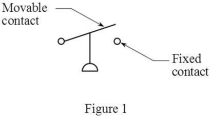
The pressure switch shown in the circuit has its movable contact above the fixed contact. Hence, the pressure switch is normally closed and kept open for the circuitry purpose. This switch is called a “normally closed held open switch”. The schematic of normally closed held open pressure switch is shown in Figure 1 below:
Thus, the correct answer is “option d. normally closed held open”.
Want to see more full solutions like this?
Subscribe now to access step-by-step solutions to millions of textbook problems written by subject matter experts!
Students have asked these similar questions
Access Pearson
Mastering Engineering
Back to my courses
Course Home
Course Home
Scores
Access Pearson
Mastering Engineering
Back to my courses
Course Home
Course Home
Scores
■Review
Next >
10. Please see attached pic.
Chapter 41 Solutions
Understanding Motor Controls
Ch. 41 - To answer the following questions refer to the...Ch. 41 - To answer the following questions refer to the...Ch. 41 - Prob. 3RQCh. 41 - To answer the following questions refer to the...Ch. 41 - To answer the following questions refer to the...Ch. 41 - Prob. 6RQCh. 41 - To answer the following questions refer to the...Ch. 41 - To answer the following questions refer to the...Ch. 41 - Prob. 9RQCh. 41 - Prob. 10RQ
Knowledge Booster


Learn more about
Need a deep-dive on the concept behind this application? Look no further. Learn more about this topic, mechanical-engineering and related others by exploring similar questions and additional content below.Similar questions
- Can you answer this question?arrow_forwardCan you answer this question?arrow_forwardA gear has a gear wheel with 16 teeth. The gear should be dimensioned for the highest and lowest gear ratio. Looking for output power, torque, speed?nin= 2000 rpmmin = 30Nmn=0,9a max= 450 mmModule 4Gear limitsz1 z213 13-1614 14-2615 15-4516 16-10117 17-131418 18-…..I have calculate but I can’t get the right answers…..√16 =459x60/56x57=1.1 lowest59x60/13x13=20,94 highestnut=2000/1.1= 1818rpmnut=2000/20.94=95.5 rpmMut=1.1x30=33 NmMut=20.94x30=628,2 Nm(Right answer)LowestZ=13, M=24,4Nm, n=2462 rpmHighestZ=92, M=172,5Nm, n=347,8 rpmP=5655W on botharrow_forward
arrow_back_ios
SEE MORE QUESTIONS
arrow_forward_ios
Recommended textbooks for you
 Understanding Motor ControlsMechanical EngineeringISBN:9781337798686Author:Stephen L. HermanPublisher:Delmar Cengage Learning
 Refrigeration and Air Conditioning Technology (Mi...Mechanical EngineeringISBN:9781305578296Author:John Tomczyk, Eugene Silberstein, Bill Whitman, Bill JohnsonPublisher:Cengage Learning
 Electrical Transformers and Rotating MachinesMechanical EngineeringISBN:9781305494817Author:Stephen L. HermanPublisher:Cengage Learning
 Welding: Principles and Applications (MindTap Cou...Mechanical EngineeringISBN:9781305494695Author:Larry JeffusPublisher:Cengage Learning
 Automotive TechnologyMechanical EngineeringISBN:9781337794213Author:ERJAVEC, Jack.Publisher:Cengage,
 Precision Machining Technology (MindTap Course Li...Mechanical EngineeringISBN:9781285444543Author:Peter J. Hoffman, Eric S. Hopewell, Brian JanesPublisher:Cengage Learning
Understanding Motor Controls
Mechanical Engineering
ISBN:9781337798686
Author:Stephen L. Herman
Publisher:Delmar Cengage Learning
Refrigeration and Air Conditioning Technology (Mi...
Mechanical Engineering
ISBN:9781305578296
Author:John Tomczyk, Eugene Silberstein, Bill Whitman, Bill Johnson
Publisher:Cengage Learning
Electrical Transformers and Rotating Machines
Mechanical Engineering
ISBN:9781305494817
Author:Stephen L. Herman
Publisher:Cengage Learning
Welding: Principles and Applications (MindTap Cou...
Mechanical Engineering
ISBN:9781305494695
Author:Larry Jeffus
Publisher:Cengage Learning
Automotive Technology
Mechanical Engineering
ISBN:9781337794213
Author:ERJAVEC, Jack.
Publisher:Cengage,
Precision Machining Technology (MindTap Course Li...
Mechanical Engineering
ISBN:9781285444543
Author:Peter J. Hoffman, Eric S. Hopewell, Brian Janes
Publisher:Cengage Learning
Physics 33 - Fluid Statics (1 of 10) Pressure in a Fluid; Author: Michel van Biezen;https://www.youtube.com/watch?v=mzjlAla3H1Q;License: Standard YouTube License, CC-BY