
COMPUTER SCIENCE ILLUMIN.-TEXT
6th Edition
ISBN: 2810016866372
Author: Dale
Publisher: JONES+BART
expand_more
expand_more
format_list_bulleted
Videos
Question
Chapter 4, Problem 61E
Program Plan Intro
Circuit:
- The circuit is known as the combination of gates that is used to achieve a difficult logical operation.
- It contains two general categories, they are:
- Combinational circuit
- Sequential circuit
Expert Solution & Answer
Explanation of Solution
Given circuit diagram:
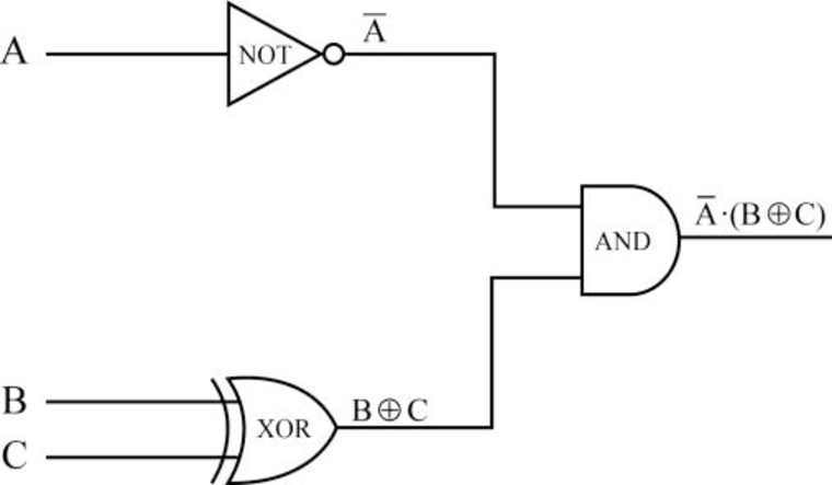
Behavior of the circuit:
- From the circuit diagram:
- First, the input A is passed to NOT gate to perform the inverse of A and produces the output as
- Next, the inputs B and C are passed into XOR gate to perform the XOR operation of the B and C to produce the output as
- Note: XOR operation - when both the inputs are the same, then the output of XOR gate is 0. Otherwise, the output of XOR gate is 1.
- Finally, the output of NOT gate and output of XOR gate is passed as the input of AND gate.
- That is, “
- That is, “
- First, the input A is passed to NOT gate to perform the inverse of A and produces the output as
Truth table:
Step 1:
- The inputs are A, B, and C for the above circuit diagram:
| A | B | C | |||
| 0 | 0 | 0 | |||
| 0 | 0 | 1 | |||
| 0 | 1 | 0 | |||
| 0 | 1 | 1 | |||
| 1 | 0 | 0 | |||
| 1 | 0 | 1 | |||
| 1 | 1 | 0 | |||
| 1 | 1 | 1 |
Step 2:
- When the inputs are A as 0, B as 0, and C as 0:
| A | B | C | |||
| 0 | 0 | 0 | 1 | 0 | 0 |
| 0 | 0 | 1 | |||
| 0 | 1 | 0 | |||
| 0 | 1 | 1 | |||
| 1 | 0 | 0 | |||
| 1 | 0 | 1 | |||
| 1 | 1 | 0 | |||
| 1 | 1 | 1 |
- First, the input A as 0 is passed to NOT gate to perform the inverse of the A and produces the output as
- Next, the inputs B as 0 and C as 0 are passed in the XOR gate to perform the XOR operation of 0 and 0, to produce the output as
- Note: XOR operation: when both the inputs are the same, the output of XOR gate is 0. Otherwise, the output of XOR gate is 1.
- Finally, the output of NOT gate and output of XOR gate are passed as the input of AND gate.
- That is, “1” and “0” are passed as input to AND gate and produces the output
- That is, “1” and “0” are passed as input to AND gate and produces the output
Step 3:
- When the inputs are A as 0, B as 0, and C as 1:
| A | B | C | |||
| 0 | 0 | 0 | 1 | 0 | 0 |
| 0 | 0 | 1 | 1 | 1 | 1 |
| 0 | 1 | 0 | |||
| 0 | 1 | 1 | |||
| 1 | 0 | 0 | |||
| 1 | 0 | 1 | |||
| 1 | 1 | 0 | |||
| 1 | 1 | 1 |
- First, the input A as 0 is passed to NOT gate to perform the inverse of the A and produces the output as
- Next, the inputs B as 0 and C as 1 are passed in the XOR gate to perform the XOR operation of 0 and 1, to produce the output as
- Note: XOR operation - when both the inputs are same, the output of XOR gate is 0. Otherwise, output of XOR gate will be 1.
- Finally, the output of NOT gate and output of XOR gate are passed as the input of AND gate.
- That is, “1” and “1” are passed as input to AND gate and produces the output
- That is, “1” and “1” are passed as input to AND gate and produces the output
Step 4:
- When the inputs are A as 0, B as 1, and C as 0:
| A | B | C | |||
| 0 | 0 | 0 | 1 | 0 | 0 |
| 0 | 0 | 1 | 1 | 1 | 1 |
| 0 | 1 | 0 | 1 | 1 | 1 |
| 0 | 1 | 1 | |||
| 1 | 0 | 0 | |||
| 1 | 0 | 1 | |||
| 1 | 1 | 0 | |||
| 1 | 1 | 1 |
- First, the input A as 0 is passed to NOT gate to perform the inverse of A and produces the output as
- Next, the inputs B as 1 and C as 0 are passed in the XOR gate to perform the XOR operation of the 1 and 0, to produce the output as
- Note: XOR operation - when both the inputs are same, the output of XOR gate is 0. Otherwise, the output of XOR gate is 1.
- Finally, the output of NOT gate and output of XOR gate are passed as the input of AND gate.
- That is, “1” and “1” are passed as input for AND gate and produces the output
- That is, “1” and “1” are passed as input for AND gate and produces the output
Step 5:
- When the inputs are A as 0, B as 1, and C as 1:
| A | B | C | |||
| 0 | 0 | 0 | 1 | 0 | 0 |
| 0 | 0 | 1 | 1 | 1 | 1 |
| 0 | 1 | 0 | 1 | 1 | 1 |
| 0 | 1 | 1 | 1 | 0 | 0 |
| 1 | 0 | 0 | |||
| 1 | 0 | 1 | |||
| 1 | 1 | 0 | |||
| 1 | 1 | 1 |
- First, the input A as 0 is passed to NOT gate to perform the inverse of the A and produces the output as
- Next, the inputs B as 1 and C as 1 are passed in the XOR gate to perform the XOR operation of the 1 and 1, to produce the output as
- Note: XOR operation - when both the inputs are same, the output of XOR gate is 0. Otherwise, the output of XOR gate is 1.
- Finally, the output of NOT gate and output of XOR gate are passed as the input of AND gate.
- That is, “1” and “0” are passed as input for AND gate and produces the output
- That is, “1” and “0” are passed as input for AND gate and produces the output
Step 6:
- When the inputs are A as 1, B as 0, and C as 0:
| A | B | C | |||
| 0 | 0 | 0 | 1 | 0 | 0 |
| 0 | 0 | 1 | 1 | 1 | 1 |
| 0 | 1 | 0 | 1 | 1 | 1 |
| 0 | 1 | 1 | 1 | 0 | 0 |
| 1 | 0 | 0 | 0 | 0 | 0 |
| 1 | 0 | 1 | |||
| 1 | 1 | 0 | |||
| 1 | 1 | 1 |
- First, the input A as 1 is passed to NOT gate to perform the inverse of the A and produces the output as
- Next, the inputs B as 0 and C as 0 are passed in the XOR gate to perform the XOR operation of the 0 and 0, to produce the output as
- Note: XOR operation - when both the inputs are same, the output of XOR gate is 0. Otherwise, the output of XOR gate is 1.
- Finally, the output of NOT gate and output of XOR gate are passed as the input of AND gate.
- That is, “0” and “0” are passed as input for AND gate and produces the output
- That is, “0” and “0” are passed as input for AND gate and produces the output
Step 7:
- When the inputs are A as 1, B as 0, and C as 1:
| A | B | C | |||
| 0 | 0 | 0 | 1 | 0 | 0 |
| 0 | 0 | 1 | 1 | 1 | 1 |
| 0 | 1 | 0 | 1 | 1 | 1 |
| 0 | 1 | 1 | 1 | 0 | 0 |
| 1 | 0 | 0 | 0 | 0 | 0 |
| 1 | 0 | 1 | 0 | 1 | 0 |
| 1 | 1 | 0 | |||
| 1 | 1 | 1 |
- First, the input A as 1 is passed to NOT gate to perform the inverse of the A and produces the output as
- Next, the inputs B as 0 and C as 1 are passed in the XOR gate to perform the XOR operation of the 0 and 0, to produce the output as
- Note: XOR operation - when both the inputs are same, the output of XOR gate is 0. Otherwise, the output of XOR gate is 1.
- Finally, the output of NOT gate and output of XOR gate are passed as the input of AND gate.
- That is, “0” and “1” are passed as input for AND gate and produces the output
- That is, “0” and “1” are passed as input for AND gate and produces the output
Step 8:
- When the inputs are A as 1, B as 1, and C as 0:
| A | B | C | |||
| 0 | 0 | 0 | 1 | 0 | 0 |
| 0 | 0 | 1 | 1 | 1 | 1 |
| 0 | 1 | 0 | 1 | 1 | 1 |
| 0 | 1 | 1 | 1 | 0 | 0 |
| 1 | 0 | 0 | 0 | 0 | 0 |
| 1 | 0 | 1 | 0 | 1 | 0 |
| 1 | 1 | 0 | 0 | 1 | 0 |
| 1 | 1 | 1 |
- First, the input A as 1 is passed to NOT gate to perform the inverse of the A and produces the output as
- Next, the inputs B as 1 and C as 0 are passed in the XOR gate to perform the XOR operation of the 0 and 0, to produce the output as
- Note: XOR operation - when both the inputs are same, the output of XOR gate is 0. Otherwise, the output of XOR gate is 1.
- Finally, the output of NOT gate and output of XOR gate are passed as the input of AND gate.
- That is, “0” and “1” are passed as input to AND gate and produces the output
- That is, “0” and “1” are passed as input to AND gate and produces the output
Step 9:
- When the inputs are A as 1, B as 1, and C as 1:
| A | B | C | |||
| 0 | 0 | 0 | 1 | 0 | 0 |
| 0 | 0 | 1 | 1 | 1 | 1 |
| 0 | 1 | 0 | 1 | 1 | 1 |
| 0 | 1 | 1 | 1 | 0 | 0 |
| 1 | 0 | 0 | 0 | 0 | 0 |
| 1 | 0 | 1 | 0 | 1 | 0 |
| 1 | 1 | 0 | 0 | 1 | 0 |
| 1 | 1 | 1 | 0 | 0 | 0 |
- First, the input A as 1 is passed to NOT gate to perform the inverse of the A and produces the output as
- Next, the inputs B as 1 and C as 1 are passed in the XOR gate to perform the XOR operation of the 0 and 0, to produce the output as
- Note: XOR operation - when both the inputs are same, the output of XOR gate is 0. Otherwise, the output of XOR gate is 1.
- Finally, the output of NOT gate and output of XOR gate are passed as the input of AND gate.
- That is, “0” and “0” are passed as input for AND gate and produces the output
- That is, “0” and “0” are passed as input for AND gate and produces the output
Therefore, Truth table for the given circuit is:
| A | B | C | |||
| 0 | 0 | 0 | 1 | 0 | 0 |
| 0 | 0 | 1 | 1 | 1 | 1 |
| 0 | 1 | 0 | 1 | 1 | 1 |
| 0 | 1 | 1 | 1 | 0 | 0 |
| 1 | 0 | 0 | 0 | 0 | 0 |
| 1 | 0 | 1 | 0 | 1 | 0 |
| 1 | 1 | 0 | 0 | 1 | 0 |
| 1 | 1 | 1 | 0 | 0 | 0 |
Want to see more full solutions like this?
Subscribe now to access step-by-step solutions to millions of textbook problems written by subject matter experts!
Students have asked these similar questions
make corrections of this program based on the errors shown. this is CIS 227 .
Create 6 users: Don, Liz, Shamir, Jose, Kate, and Sal.
Create 2 groups: marketing and research.
Add Shamir, Jose, and Kate to the marketing group.
Add Don, Liz, and Sal to the research group.
Create a shared directory for each group.
Create two files to put into each directory:
spreadsheetJanuary.txt
meetingNotes.txt
Assign access permissions to the directories:
Groups should have Read+Write access
Leave owner permissions as they are
“Everyone else” should not have any access
Submit for grade:
Screenshot of /etc/passwd contents showing your new users
Screenshot of /etc/group contents showing new groups with their members
Screenshot of shared directories you created with files and permissions
⚫ your circuit diagrams for your basic bricks, such as AND, OR, XOR gates and 1 bit multiplexers,
⚫ your circuit diagrams for your extended full adder, designed in Section 1 and
⚫ your circuit diagrams for your 8-bit arithmetical-logical unit, designed in Section 2.
1 An Extended Full Adder
In this Section, we are going to design an extended full adder circuit (EFA). That EFA takes 6 one bit inputs: aj, bj,
Cin, Tin, t₁ and to. Depending on the four possible combinations of values on t₁ and to, the EFA produces 3 one bit
outputs: sj, Cout and rout.
The EFA can be specified in principle by a truth table with 26 = 64 entries and 3 outputs. However, as the EFA
ignores certain inputs in certain cases, it is easier to work with the following overview specification, depending only
on t₁ and to in the first place:
t₁ to Description
00
Output Relationship
Ignored
Inputs
Addition Mode
2 Coutsjaj + bj + Cin, Tout= 0
Tin
0 1
Shift Left Mode
Sj = Cin,
Cout=bj, rout = 0
rin, aj
10
1 1
Shift Right…
Chapter 4 Solutions
COMPUTER SCIENCE ILLUMIN.-TEXT
Ch. 4 - Prob. 1ECh. 4 - Prob. 2ECh. 4 - Prob. 3ECh. 4 - Prob. 4ECh. 4 - Prob. 5ECh. 4 - Prob. 6ECh. 4 - Prob. 7ECh. 4 - Prob. 8ECh. 4 - Prob. 9ECh. 4 - Prob. 10E
Ch. 4 - Prob. 11ECh. 4 - Prob. 12ECh. 4 - Prob. 13ECh. 4 - Prob. 14ECh. 4 - Prob. 15ECh. 4 - Prob. 16ECh. 4 - Prob. 17ECh. 4 - Prob. 18ECh. 4 - Prob. 19ECh. 4 - Prob. 20ECh. 4 - Prob. 21ECh. 4 - Prob. 22ECh. 4 - Prob. 23ECh. 4 - Prob. 24ECh. 4 - Prob. 25ECh. 4 - Prob. 26ECh. 4 - Prob. 27ECh. 4 - Prob. 28ECh. 4 - Prob. 29ECh. 4 - Prob. 30ECh. 4 - Prob. 31ECh. 4 - Prob. 32ECh. 4 - Prob. 33ECh. 4 - Prob. 34ECh. 4 - Prob. 35ECh. 4 - Prob. 36ECh. 4 - Prob. 37ECh. 4 - Prob. 38ECh. 4 - Prob. 39ECh. 4 - Prob. 40ECh. 4 - Prob. 41ECh. 4 - Prob. 42ECh. 4 - Prob. 43ECh. 4 - Prob. 44ECh. 4 - Prob. 45ECh. 4 - Prob. 46ECh. 4 - Prob. 47ECh. 4 - Prob. 48ECh. 4 - Prob. 49ECh. 4 - Prob. 50ECh. 4 - Prob. 51ECh. 4 - Prob. 52ECh. 4 - Prob. 53ECh. 4 - Prob. 54ECh. 4 - Prob. 55ECh. 4 - Prob. 56ECh. 4 - Prob. 57ECh. 4 - Prob. 58ECh. 4 - Prob. 59ECh. 4 - Prob. 60ECh. 4 - Prob. 61ECh. 4 - Prob. 62ECh. 4 - Prob. 63ECh. 4 - Prob. 64ECh. 4 - Prob. 65ECh. 4 - Prob. 66ECh. 4 - Prob. 67ECh. 4 - Prob. 68ECh. 4 - Prob. 69ECh. 4 - Prob. 70ECh. 4 - Prob. 71ECh. 4 - Prob. 72ECh. 4 - Prob. 73ECh. 4 - Prob. 1TQCh. 4 - Prob. 2TQCh. 4 - Prob. 3TQCh. 4 - Prob. 4TQ
Knowledge Booster


Learn more about
Need a deep-dive on the concept behind this application? Look no further. Learn more about this topic, computer-science and related others by exploring similar questions and additional content below.Similar questions
- Show the correct stereochemistry when needed!! mechanism: mechanism: Show the correct stereochemistry when needed!! Br NaOPh diethyl ether substitutionarrow_forwardIn javaarrow_forwardKeanPerson #keanld:int #keanEmail:String #firstName:String #lastName: String KeanAlumni -yearOfGraduation: int - employmentStatus: String + KeanPerson() + KeanPerson(keanld: int, keanEmail: String, firstName: String, lastName: String) + getKeanld(): int + getKeanEmail(): String +getFirstName(): String + getLastName(): String + setFirstName(firstName: String): void + setLastName(lastName: String): void +toString(): String +getParkingRate(): double + KeanAlumni() + KeanAlumni(keanld: int, keanEmail: String, firstName: String, lastName: String, yearOfGraduation: int, employmentStatus: String) +getYearOfGraduation(): int + setYearOfGraduation(yearOfGraduation: int): void +toString(): String +getParkingRate(): double In this question, write Java code to Create and Test the superclass: Abstract KeanPerson and a subclass of the KeanPerson: KeanAlumni. Task 1: Implement Abstract Class KeanPerson using UML (10 points) • Four data fields • Two constructors (1 default and 1 constructor with all…arrow_forward
- Plz correct answer by best experts...??arrow_forwardQ3) using the following image matrix a- b- 12345 6 7 8 9 10 11 12 13 14 15 1617181920 21 22 23 24 25 Using direct chaotic one dimension method to convert the plain text to stego text (hello ahmed)? Using direct chaotic two-dimension method to convert the plain text to stego text?arrow_forward: The Multithreaded Cook In this lab, we'll practice multithreading. Using Semaphores for synchronization, implement a multithreaded cook that performs the following recipe, with each task being contained in a single Thread: 1. Task 1: Cut onions. a. Waits for none. b. Signals Task 4 2. Task 2: Mince meat. a. Waits for none b. Signals Task 4 3. Task 3: Slice aubergines. a. Waits for none b. Signals Task 6 4. Task 4: Make sauce. a. Waits for Task 1, and 2 b. Signals Task 6 5. Task 5: Finished Bechamel. a. Waits for none b. Signals Task 7 6. Task 6: Layout the layers. a. Waits for Task 3, and 4 b. Signals Task 7 7. Task 7: Put Bechamel and Cheese. a. Waits for Task 5, and 6 b. Signals Task 9 8. Task 8: Turn on oven. a. Waits for none b. Signals Task 9 9. Task 9: Cook. a. Waits for Task 7, and 8 b. Signals none At the start of each task (once all Semaphores have been acquired), print out a string of the task you are starting, sleep for 2-11 seconds, then print out a string saying that you…arrow_forward
- Programming Problems 9.28 Assume that a system has a 32-bit virtual address with a 4-KB page size. Write a C program that is passed a virtual address (in decimal) on the command line and have it output the page number and offset for the given address. As an example, your program would run as follows: ./addresses 19986 Your program would output: The address 19986 contains: page number = 4 offset = 3602 Writing this program will require using the appropriate data type to store 32 bits. We encourage you to use unsigned data types as well. Programming Projects Contiguous Memory Allocation In Section 9.2, we presented different algorithms for contiguous memory allo- cation. This project will involve managing a contiguous region of memory of size MAX where addresses may range from 0 ... MAX - 1. Your program must respond to four different requests: 1. Request for a contiguous block of memory 2. Release of a contiguous block of memory 3. Compact unused holes of memory into one single block 4.…arrow_forwardusing r languagearrow_forwardProgramming Problems 9.28 Assume that a system has a 32-bit virtual address with a 4-KB page size. Write a C program that is passed a virtual address (in decimal) on the command line and have it output the page number and offset for the given address. As an example, your program would run as follows: ./addresses 19986 Your program would output: The address 19986 contains: page number = 4 offset = 3602 Writing this program will require using the appropriate data type to store 32 bits. We encourage you to use unsigned data types as well. Programming Projects Contiguous Memory Allocation In Section 9.2, we presented different algorithms for contiguous memory allo- cation. This project will involve managing a contiguous region of memory of size MAX where addresses may range from 0 ... MAX - 1. Your program must respond to four different requests: 1. Request for a contiguous block of memory 2. Release of a contiguous block of memory 3. Compact unused holes of memory into one single block 4.…arrow_forward
- using r languagearrow_forwardWrite a function to compute a Monte Carlo estimate of the Beta(3, 3) cdf, and use the function to estimate F(x) for x = 0.1,0.2,...,0.9. Compare the estimates with the values returned by the pbeta function in R.arrow_forwardWrite a function to compute a Monte Carlo estimate of the Gamma(r = 3, λ = 2) cdf, and use the function to estimate F(x) for x = 0.2, 0.4, . . . , 2.0. Compare the estimates with the values returned by the pgamma function in R.arrow_forward
arrow_back_ios
SEE MORE QUESTIONS
arrow_forward_ios
Recommended textbooks for you
 Database System ConceptsComputer ScienceISBN:9780078022159Author:Abraham Silberschatz Professor, Henry F. Korth, S. SudarshanPublisher:McGraw-Hill Education
 Starting Out with Python (4th Edition)Computer ScienceISBN:9780134444321Author:Tony GaddisPublisher:PEARSON
 Digital Fundamentals (11th Edition)Computer ScienceISBN:9780132737968Author:Thomas L. FloydPublisher:PEARSON
 C How to Program (8th Edition)Computer ScienceISBN:9780133976892Author:Paul J. Deitel, Harvey DeitelPublisher:PEARSON
 Database Systems: Design, Implementation, & Manag...Computer ScienceISBN:9781337627900Author:Carlos Coronel, Steven MorrisPublisher:Cengage Learning
 Programmable Logic ControllersComputer ScienceISBN:9780073373843Author:Frank D. PetruzellaPublisher:McGraw-Hill Education
Database System Concepts
Computer Science
ISBN:9780078022159
Author:Abraham Silberschatz Professor, Henry F. Korth, S. Sudarshan
Publisher:McGraw-Hill Education
Starting Out with Python (4th Edition)
Computer Science
ISBN:9780134444321
Author:Tony Gaddis
Publisher:PEARSON
Digital Fundamentals (11th Edition)
Computer Science
ISBN:9780132737968
Author:Thomas L. Floyd
Publisher:PEARSON
C How to Program (8th Edition)
Computer Science
ISBN:9780133976892
Author:Paul J. Deitel, Harvey Deitel
Publisher:PEARSON
Database Systems: Design, Implementation, & Manag...
Computer Science
ISBN:9781337627900
Author:Carlos Coronel, Steven Morris
Publisher:Cengage Learning
Programmable Logic Controllers
Computer Science
ISBN:9780073373843
Author:Frank D. Petruzella
Publisher:McGraw-Hill Education
Boolean Algebra - Digital Logic and Logic Families - Industrial Electronics; Author: Ekeeda;https://www.youtube.com/watch?v=u7XnJos-_Hs;License: Standard YouTube License, CC-BY
Boolean Algebra 1 – The Laws of Boolean Algebra; Author: Computer Science;https://www.youtube.com/watch?v=EPJf4owqwdA;License: Standard Youtube License