Concept explainers
Find the force in each bar and mention the force is tension or compression of the bars in the truss.
Explanation of Solution
Assumptions:
- Consider the state of bars as tension (T) where the force is pulling the bar and as compression (C) where the force is pushing the bar.
- The sign of the force in the bar is positive when the force is in tension and negative when the force is in compression.
- Consider the force indicating right side as positive and left side as negative in horizontal components of forces.
- Consider the force indicating upward is taken as positive and downward as negative in vertical components of forces.
- Consider clockwise moment as negative and anti-clock wise moment as positive wherever applicable.
Show the free-body diagram of the entire truss as in Figure 1.
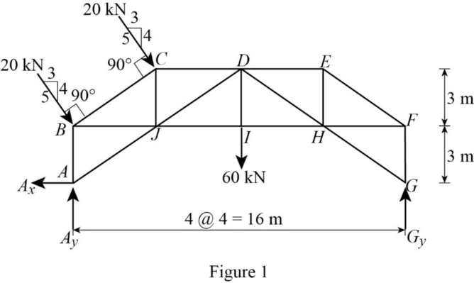
Find the horizontal reaction at point A by resolving the horizontal component of forces.
Find the vertical reaction at point G by taking moment about point A.
Find the vertical reaction at point A by resolving the vertical component of forces.
Consider the joint G;
Show the forces acting at the joint G as in Figure 2.
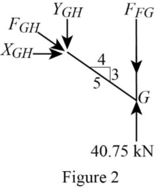
Resolve the horizontal component of forces.
Use the proportion:
Resolve the vertical component of forces.
Consider the joint F;
Show the forces acting at the joint F as in Figure 3.
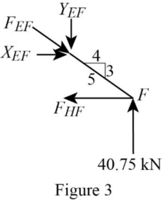
Resolve the vertical component of forces.
Use the proportion:
Resolve the horizontal component of forces.
Consider the joint E;
Show the forces acting at the joint E as in Figure 4.
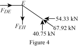
Resolve the vertical component of forces.
Resolve the horizontal component of forces.
Consider the joint H;
Show the forces acting at the joint H as in Figure 5.
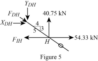
Resolve the vertical component of forces.
Use the proportion:
Resolve the horizontal component of forces.
Consider the joint I;
Show the forces acting at the joint I as in Figure 6.
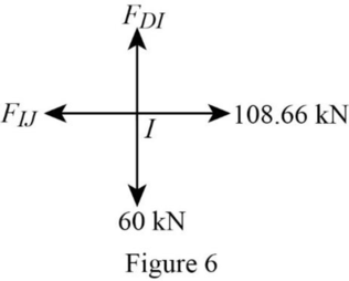
Resolve the vertical component of forces.
Resolve the horizontal component of forces.
Consider the joint D;
Show the forces acting at the joint D as in Figure 7.
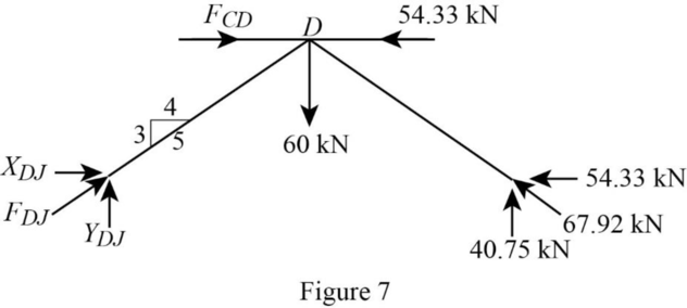
Resolve the vertical component of forces.
Use the proportion:
Resolve the horizontal component of forces.
Consider the joint C;
Show the forces acting at the joint C as in Figure 8.
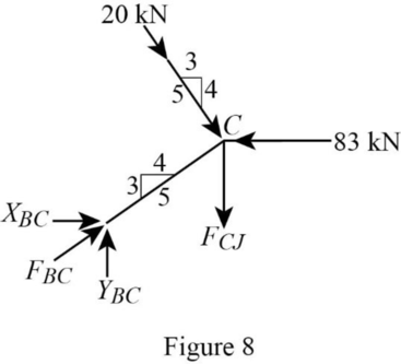
Resolve the horizontal component of forces.
Use the proportion:
Resolve the vertical component of forces.
Consider the joint J;
Show the forces acting at the joint J as in Figure 9.
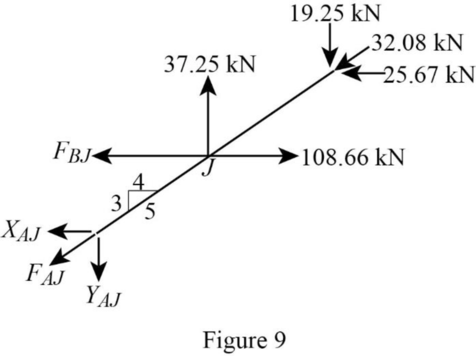
Resolve the vertical component of forces.
Use the proportion:
Resolve the horizontal component of forces.
Consider the joint A;
Show the forces acting at the joint A as in Figure 10.
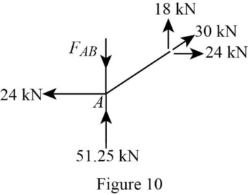
Resolve the vertical component of forces.
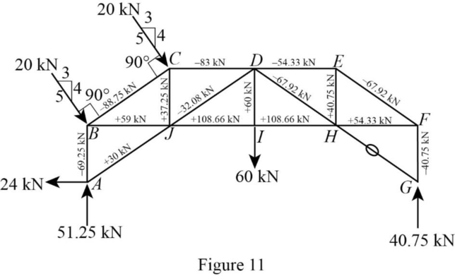
Show the forces in the bars of the truss as in Figure 11.
Want to see more full solutions like this?
Chapter 4 Solutions
Fundamentals of Structural Analysis


- 6. A lake with no outlet is fed by a river with a constant flow of 1200 ft3/s. Water evaporates from the surface at a constant rate of 13 ft3/s per square mile of surface area. The surface area varies with the depth h (in feet) as A (square miles) = 4.5 + 5.5h. What is the equilibrium depth of the lake? Below what river discharge (volume flow rate) will the lake dry up?arrow_forwardProblem 5 (A, B, C and D are fixed). Find the reactions at A and D 8 k B 15 ft A -20 ft C 10 ft Darrow_forwardProblem 4 (A, B, E, D and F are all pin connected and C is fixed) Find the reactions at A, D and F 8 m B 6m E 12 kN D F 4 marrow_forward
- Problem 1 (A, C and D are pins) Find the reactions and A, C and D. D 6 m B 12 kN/m 8 m A C 6 marrow_forwardUniform Grade of Pipe Station of Point A is 9+50.00. Elevation Point A = 250.75.Station of Point B is 13+75.00. Elevation Point B = 244.10 1) Calculate flowline of pipe elevations at every 50 ft. interval (Half Station). 2) Tabulate station and elevation for each station like shown on example 3) Draw Sketcharrow_forward40m 150N B 40marrow_forward
- Note: Please accurately answer it!. I'll give it a thumbs up or down based on the answer quality and precision. Question: What is the group name of Sample B in problem 3 from the image?. By also using the ASTM flow chart!. This unit is soil mechanics btwarrow_forwardPick the rural location of a project site in Victoria, and its catchment area-not bigger than 25 sqkm, and given the below information, determine the rainfall intensity for ARI = 5, 50, 100 year storm event. Show all the details of the procedure. Each student must propose different length of streams and elevations. Use fig below as a sample only. Pt. E-ht. 95.0 200m 600m PLD-M. 91.0 300m Pt. C-93.0 300m PL.B-ht. 92.0 PL.F-ht. 96.0 500m Pt. A-M. 91.00 To be deemed satisfactory the solution must include: Q.F1.1.Choice of catchment location Q.F1.2. A sketch displaying length of stream and elevation Q.F1.3. Catchment's IFD obtained from the Buro of Metheorology for specified ARI Q.F1.4.Calculation of the time of concentration-this must include a detailed determination of the equivalent slope. Q.F1.5.Use must be made of the Bransby-Williams method for the determination of the equivalent slope. Q.F1.6.The graphical display of the estimation of intensities for ARI 5,50, 100 must be shown.arrow_forwardQUANTITY SURVEYINGarrow_forward

 Structural Analysis (10th Edition)Civil EngineeringISBN:9780134610672Author:Russell C. HibbelerPublisher:PEARSON
 Principles of Foundation Engineering (MindTap Cou...Civil EngineeringISBN:9781337705028Author:Braja M. Das, Nagaratnam SivakuganPublisher:Cengage Learning
 Fundamentals of Structural AnalysisCivil EngineeringISBN:9780073398006Author:Kenneth M. Leet Emeritus, Chia-Ming Uang, Joel LanningPublisher:McGraw-Hill Education
 Traffic and Highway EngineeringCivil EngineeringISBN:9781305156241Author:Garber, Nicholas J.Publisher:Cengage Learning