Concept explainers
Find the force in each bar and mention the force is tension or compression of the bars in the truss.
Explanation of Solution
Assumptions:
- Consider the state of bars as tension (T) where the force is pulling the bar and as compression (C) where the force is pushing the bar.
- The sign of the force in the bar is positive when the force is in tension and negative when the force is in compression.
- Consider the force indicating right side as positive and left side as negative in horizontal components of forces.
- Consider the force indicating upward is taken as positive and downward as negative in vertical components of forces.
- Consider clockwise moment as negative and anti-clock wise moment as positive wherever applicable.
Show the free-body diagram of the entire truss as in Figure 1.
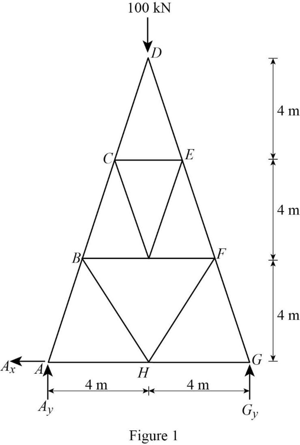
Find the vertical reaction at point G by taking moment about point A.
Find the vertical reaction at point A by resolving the vertical component of forces.
Find the horizontal reaction at point A by resolving the horizontal component of forces.
Consider the joint G;
Show the forces acting at the joint G as in Figure 2.
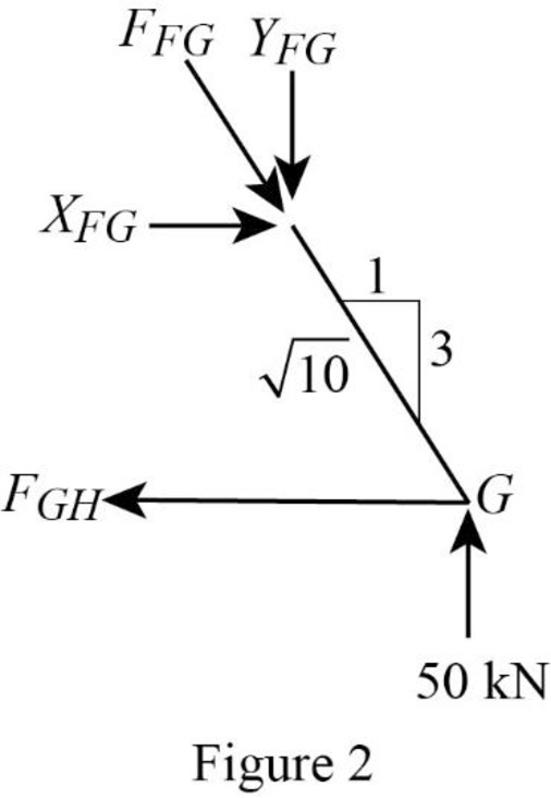
Resolve the vertical component of forces.
Use the proportion:
Resolve the horizontal component of forces.
Consider the joint A;
Show the forces acting at the joint A as in Figure 3.
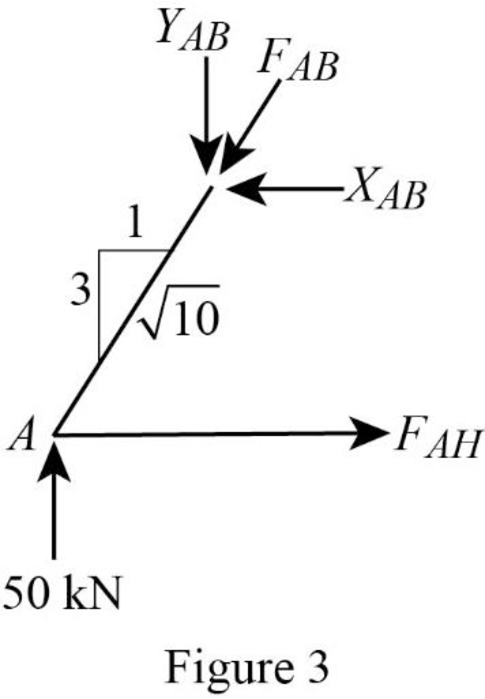
Resolve the vertical component of forces.
Use the proportion:
Resolve the horizontal component of forces.
Consider the joint H;
Show the forces acting at the joint H as in Figure 4.
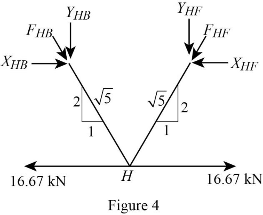
Resolve the horizontal component of forces.
Resolve the vertical component of forces.
Use the proportion:
Substitute
Substitute
Solve the Equation (3) and (4);
Consider the joint B;
Show the forces acting at the joint B as in Figure 5.
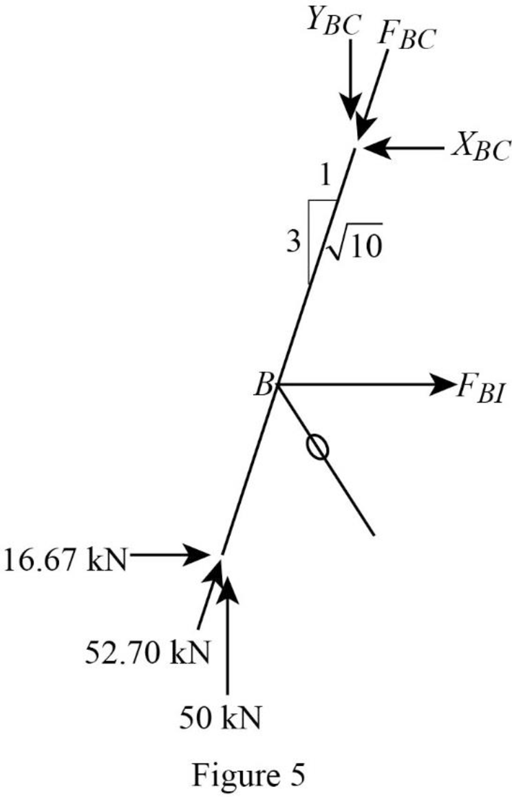
Resolve the vertical component of forces.
Use the proportion:
Resolve the horizontal component of forces.
Consider the joint F;
Show the forces acting at the joint F as in Figure 6.
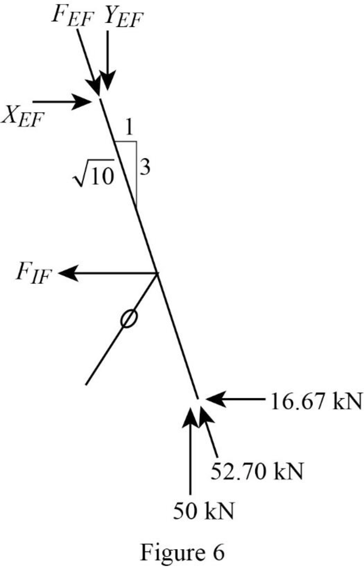
Resolve the vertical component of forces.
Use the proportion:
Resolve the horizontal component of forces.
Consider the joint I;
Show the forces acting at the joint I as in Figure 7.
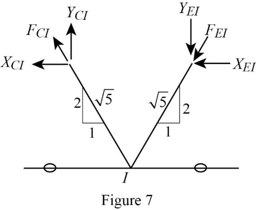
Resolve the horizontal component of forces.
Resolve the vertical component of forces.
Use the proportion:
Substitute
Substitute
Solve the Equation (7) and (8);
Consider the joint C;
Show the forces acting at the joint C as in Figure 8.

Resolve the vertical component of forces.
Use the proportion:
Resolve the horizontal component of forces.
Consider the joint E;
Show the forces acting at the joint E as in Figure 9.
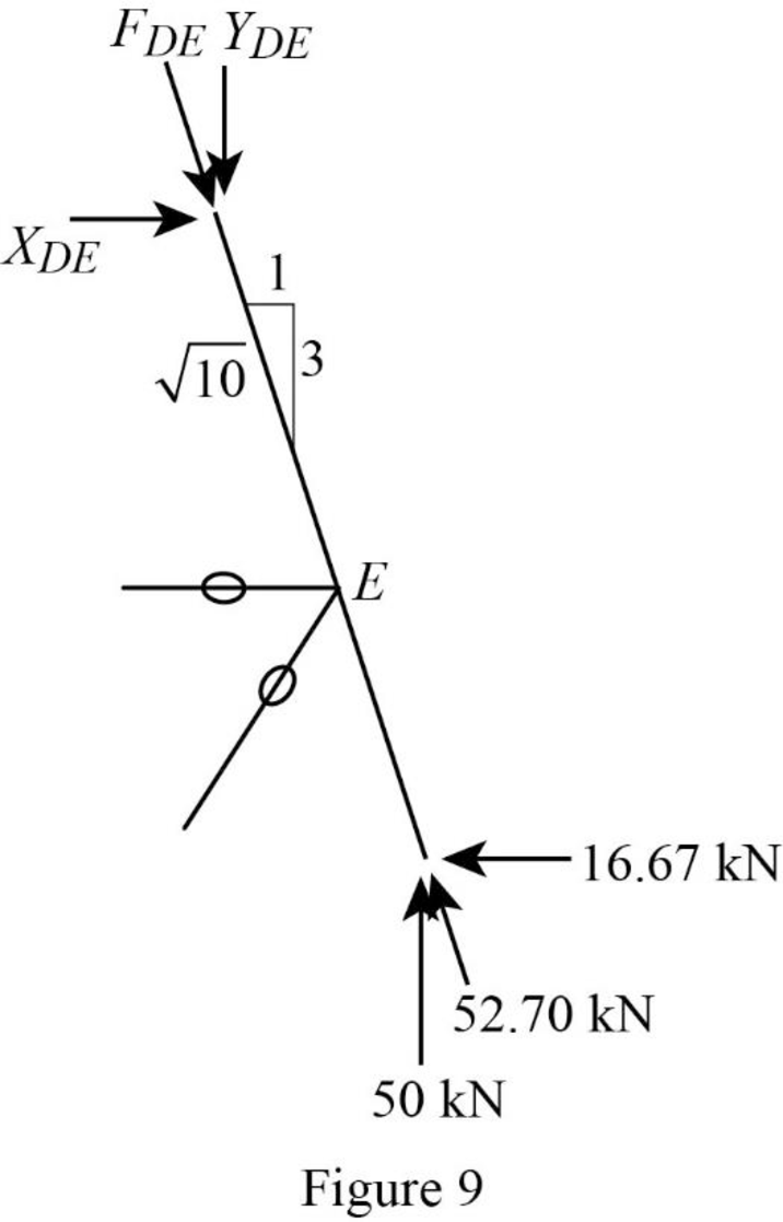
Resolve the vertical component of forces.
Use the proportion:
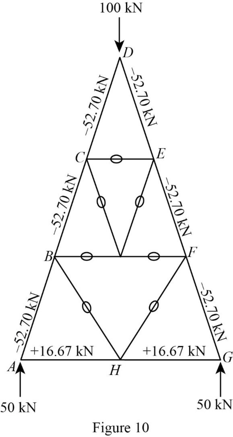
Show the forces in the bars of the truss as in Figure 10.
Want to see more full solutions like this?
Chapter 4 Solutions
Fundamentals of Structural Analysis


- You are an engineer designing an aeration tank for a wastewater treatment plant receiving municipal waste. The activated sludge system (aeration tank and secondary clarifier) you design needs to remove 85% of the incoming BODs from the primary effluent, giving a final concentration of 30.0 mg BOD5/L exiting the system. Your design will maintain a concentration of 2500 mg VSS/L and F/M ratio of 0.5 g BOD/g VSS d in the aeration tank. In an effort to keep the waste activated sludge low in water, only about 0.1% of the primary effluent flow (Q) exits the WAS line. The secondary effluent has a flow rate of 9990 m³/d. What volume (in m³) will the aeration tank need to be? Write out all equations and state any assumptions as needed. Primary effluent: Aeration tank V, X, S Secondary clarifier Secondary effluent: Q. Xo. So Qe, Xe, S 0 po RAS line: Q, X., S Activated sludge control volume WAS line: Qw, X, Sarrow_forwardAum A waste incinerator stack emits 27,027 kg/yr of cadmium and has an effective stack might of 100 m. The wind speed is 5 m/s at an anemometer located at 10 m. It is a clear sunny day with the sun nearly overhead (Class B conditions). a. Calculate the ground-level cadmium concentration (in ug/m³) at a distance of 2 km directly downwind? [Refer to tables in the textbook to help with this problem] What is the concentration of cadmium (in µg/m³) inside of a house at the location in part (a) after two hours? Note that the initial concentration of cadmium in the house was zero, there are 0.25 air changes per hour (ach), there is no source of cadmium inside the house, and cadmium is considered a conservative pollutant.arrow_forward6. A simply supported beam is subjected to uniformly distributed loads: a service dead load WD = 5 kips/ft and a service live load w₁ =7 kips/ft. Use the load combination w₁ = 1.2WD + 1.6WL. Note that the shear force is expressed as V₂ = w₁ (-/-- x) where x is the distance from a support. (65pts total) The beam also has the following properties. f = 4ksi, fy = fyt = 60 ksi, b = 18 in, h = 26 in, d = 24.5 in, 20ft No. 4 bars, U-stirrups used, Normalweight concrete (1) Calculate the required spacing of stirrups. (15pts) (2) Calculate the maximum spacing. Also, determine the location along the beam where the maximum spacing can be applied (i.e., the distance from support). (10pts) (3) Show the stirrup designs along with the shear force diagram. Indicate the numbers and spacings of stirrups. A transition between the required spacing and the maximum spacing is unnecessary. (15pts) (4) Assume the live load decreases, and, as a result, the factored shear force is 30 kips. Discuss whether…arrow_forward
- 5. A singly reinforced beam has a width b = 16 in., a height h = 20 in., and an effective depth d = 18.5 in. The beam is reinforced with six No. 8 bars. The beam is subjected to a positive bending moment, causing the bottom of the beam to experience tension. (65pts total) The material properties are as follows: f = 5 ksi, fy = 60 ksi d 888 Six no. 8 bars (1) Find the bending moment [kips-in] that can cause tension cracks. Use the following parameters regarding the equivalent transformed section. Do not consider load and resistance factors. (15pts) - Neutral axis: 10.7 in. from the top face of beam - Moment of inertia: 12,550 in² around the neutral axis - Modulus of rupture: fƒ„ = 7.5√ƒ! [psi] (i.e., the concrete tensile stress for crack initiation) (2) Find the service moment strength [kips-in]. The allowable stress of concrete and steel is 0.45f, and 0.5fy, respectively. Do not consider load and resistance factors. (15pts) (3) Calculate the nominal moment strength M, and the design…arrow_forwardQ2) Determine the bar forces and reactions of the truss. ABD= 4 in², A= 2 in² and E=30000 kips/in². A D 20 ft 60 kips 15 ft Barrow_forwardL h Water Fig. P4 Hinge Farrow_forward
- Someone wants to study environmental engineering in a European country for 8 years and wants to deposit an amount of money in one of the approved banks for the purpose of paying his annual study expenses, where it is planned that he will withdraw $2000 annually after one year from the date of deposit for a period of five consecutive years, and then withdraw $3000 annually for the remaining period of his studies. Calculate the amount required to be deposited for the purpose of covering the study expenses if you know that the interest rate is 8.5%arrow_forwardDesign a typical girder for the floor system shown in the figure below. In addition to the weight of the beam, the dead load consists of a 5-inch-thick reinforced concrete slab (normal-weight concrete). The live load is 85 psf, and there is a 20-psf partition load. Do not check deflections. Assume that the girder is supporting beams on each side, and assume that the beams weigh 35 lb / ft. Let all the loads on the girder act as a uniform load (be sure to include the weight of the beams). 30' A -4 @ 5' = 20' Use the table below. - Mn (ft-kips) Mn/ (ft-kips) | Vn (kips) Vn/v (kips) Shape W21 × 48 398 265 216 144 W12 × 58 324 216 132 87.8 W16 × 45 309 205 167 111 W18 × 40 294 196 169 113 a. Use LRFD. Calculate the required moment strength and the maximum shear. (Express your answers to three significant figures.) Mu - Vu Select a shape: -Select- b. Use ASD. ft-kips kips Calculate the required moment strength and the maximum shear. (Express your answers to three significant figures.) Ma =…arrow_forwardWater in a tank is used to control the water pressure in a pipe as shown in Figure P5 below. Find the pressure in the pipe at A if h = 200 mm and the mercury is at the elevation shown (between points B and C). Assume standard atmospheric pressure and neglect the diameter of the pipe. Express your answer in kPa.arrow_forward
- Select a W-shape for the following conditions: Beam spacing = 12 ft Span length = 25 ft Slab and deck combination weight = 43 psf Partition load = 20 psf Ceiling weight = 5 psf Flooring weight = 2 psf Live load 160 psf Fy = 50 ksi The maximum live load deflection cannot exceed L/340. Shape Mp (ft-kips) M₁/ (ft-kips) Vn (kips) Vn/v (kips) Ix (in. Vn/n, (kips) I. (in.) W14 × 61 383 254 156 104 640 W21 × 44 358 238 217 145 843 W16 × 50 345 230 186 124 659 W18 × 46 340 226 195 130 712 a. Use LRFD. Calculate the required moment of inertia, the required moment strength, and the maximum shear. (Express your answers to three significant figures.) Ix = in. 4 Μι = Vu Select a shape: -Select- b. Use ASD. ft-kips kips Calculate the required moment of inertia, the required moment strength, and the maximum shear. (Express your answers to three significant figures.) Ix Ma = Va = Select a shape: -Select- 4 in. ft-kips kipsarrow_forwardThe beam shown in the figure below has continuous lateral support of both flanges. The uniform load is a service load consisting of 70% dead load and 30% live load. The dead load includes the weight of the beam. 6 k/ft +9 18' If A992 steel is used, is a W12 × 35 adequate? For A992 steel: Fy = 50 ksi. bf h For W12 x 35: = 6.31, = 36.2 in., Zx 2tf tw (Express your answers to three significant figures.) a. Use LRFD. Mu Фомп = ft-kips ft-kips A W12 × 35 is -Select- b. Use ASD. Ma = ft-kips Mn ft-kips 26 A W12 × 35 is -Select- = +6→ 51.2 in. 3arrow_forwardVerify the value of Zx for a W10 × 30 that is tabulated in the dimensions and properties tables in Part 1 of the Manual. For W10 × 30: Ag Use the table below. - 8.84 in.2, d 10.5 in. AISC Manual Label y (in.) WT 9 × 25 2.12 WT 8 × 25 1.89 WT 7 × 24 1.35 WT 6 × 25 1.17 WT 5 × 15 1.10 (Express your answer to three significant figures.) Zx = 3 in.arrow_forward

 Structural Analysis (10th Edition)Civil EngineeringISBN:9780134610672Author:Russell C. HibbelerPublisher:PEARSON
 Principles of Foundation Engineering (MindTap Cou...Civil EngineeringISBN:9781337705028Author:Braja M. Das, Nagaratnam SivakuganPublisher:Cengage Learning
 Fundamentals of Structural AnalysisCivil EngineeringISBN:9780073398006Author:Kenneth M. Leet Emeritus, Chia-Ming Uang, Joel LanningPublisher:McGraw-Hill Education
 Traffic and Highway EngineeringCivil EngineeringISBN:9781305156241Author:Garber, Nicholas J.Publisher:Cengage Learning