
(a)
To select:
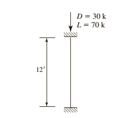
American standard channel for the given compression member using LRFD.
Answer to Problem 4.8.4P
Explanation of Solution
Given information:
Given compression member is :

Calculation:
Calculate the factored load by LRFD by using the equation.
Here
Substitute
Try a C section
AISC must be used, as this shape is non slender and is neither a double angle nor a tee shape
Check the effective slenderness ratio about y-axis using the formula.
Here K is the effective length factor
L is the length of the member between the supports.
r is the radius of gyration
Take the properties steel from the AISC steel table. K value depends on the end conditions
Calculate the elastic buckling stress using the formula.
Check for slenderness ratio by using the formula.
Here
Substitute
Since
Calculate the nominal compressive strength of column using the formula.
Substitute,
=
=
Calculate design strength of the column using by LRFD method
Here we have
Check the effective slenderness ratio about x-axis using the formula.
Substitute
From the manual companion CD:
Calculate the elastic buckling stress using the formula.
Calculate the value of
Calculate the total stress by equation
Calculate the value of
In order to determine which compressive strength equation to be use, compare the value of
Since
Calculate the maximum strength by using the formula.
.
Conclusion:
(b)
To select:
American standard channel for the given compression member using ASD.
Answer to Problem 4.8.4P
Explanation of Solution
Given information:
Given compression member is
Calculation:
Calculate the factored load by LRFD by using the equation.
He re
Substitute
Try a C section
AISC must be used, as this shape is non slender and is neither a double angle nor a tee shape
Check the effective slenderness ratio about y-axis using the formula
Here K is the effective length factor
L is the length of the member between the supports
r is the radius of gyration
Take the properties steel from the AISC steel table. K value depends on the end conditions
Calculate the elastic buckling stress using the formula.
Check for slenderness ratio by using the formula.
Here
Substitute
Since
Calculate the nominal compressive strength of column using the formula.
Substitute,
=
=
Calculate design strength of the column using by ASD method.
Here we have
Check the effective slenderness ratio about x-axis using the formula.
Substitute
From the manual companion CD:
Calculate the elastic buckling stress using the formula.
Calculate the value of
Calculate the total stress by equation
Calculate the value of
In order to determine which compressive strength equation to be use, compare the value of
Since
Calculate the maximum strength by using the formula.
Conclusion:
Want to see more full solutions like this?
Chapter 4 Solutions
STEEL DESIGN W/ ACCESS

- Calculate the BMs (bending moments) at all the joints of the beam shown in Fig.1 using the slope deflection method, draw the resulting shear force diagran and bending moment diagram. The beam is subjected to an UDL of w=65m. L=4.5m, L1= 1.8m. Assume the support at C is pinned, and A and B are roller supports. E = 200 GPa, I = 250x106 mm4.arrow_forwardProblem 2 (A is fixed and C is a pin) Find the reactions and A and C. 10 k- 6 ft 6 ft B A 2 k/ft 15 ftarrow_forward6. A lake with no outlet is fed by a river with a constant flow of 1200 ft3/s. Water evaporates from the surface at a constant rate of 13 ft3/s per square mile of surface area. The surface area varies with the depth h (in feet) as A (square miles) = 4.5 + 5.5h. What is the equilibrium depth of the lake? Below what river discharge (volume flow rate) will the lake dry up?arrow_forward
- Problem 5 (A, B, C and D are fixed). Find the reactions at A and D 8 k B 15 ft A -20 ft C 10 ft Darrow_forwardProblem 4 (A, B, E, D and F are all pin connected and C is fixed) Find the reactions at A, D and F 8 m B 6m E 12 kN D F 4 marrow_forwardProblem 1 (A, C and D are pins) Find the reactions and A, C and D. D 6 m B 12 kN/m 8 m A C 6 marrow_forward
- Uniform Grade of Pipe Station of Point A is 9+50.00. Elevation Point A = 250.75.Station of Point B is 13+75.00. Elevation Point B = 244.10 1) Calculate flowline of pipe elevations at every 50 ft. interval (Half Station). 2) Tabulate station and elevation for each station like shown on example 3) Draw Sketcharrow_forward40m 150N B 40marrow_forwardquantity surveyingarrow_forward
- Quantity Surveyingarrow_forwardquantity surveyingarrow_forwardNote: Please accurately answer it!. I'll give it a thumbs up or down based on the answer quality and precision. Question: What is the group name of Sample B in problem 3 from the image?. By also using the ASTM flow chart!. This unit is soil mechanics btwarrow_forward
 Steel Design (Activate Learning with these NEW ti...Civil EngineeringISBN:9781337094740Author:Segui, William T.Publisher:Cengage Learning