
(a)
To select:
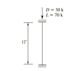
American standard channel for the given compression member using LRFD.
Answer to Problem 4.8.4P
Explanation of Solution
Given information:
Given compression member is :

Calculation:
Calculate the factored load by LRFD by using the equation.
Here
Substitute
Try a C section
AISC must be used, as this shape is non slender and is neither a double angle nor a tee shape
Check the effective slenderness ratio about y-axis using the formula.
Here K is the effective length factor
L is the length of the member between the supports.
r is the radius of gyration
Take the properties steel from the AISC steel table. K value depends on the end conditions
Calculate the elastic buckling stress using the formula.
Check for slenderness ratio by using the formula.
Here
Substitute
Since
Calculate the nominal compressive strength of column using the formula.
Substitute,
=
=
Calculate design strength of the column using by LRFD method
Here we have
Check the effective slenderness ratio about x-axis using the formula.
Substitute
From the manual companion CD:
Calculate the elastic buckling stress using the formula.
Calculate the value of
Calculate the total stress by equation
Calculate the value of
In order to determine which compressive strength equation to be use, compare the value of
Since
Calculate the maximum strength by using the formula.
.
Conclusion:
(b)
To select:
American standard channel for the given compression member using ASD.
Answer to Problem 4.8.4P
Explanation of Solution
Given information:
Given compression member is
Calculation:
Calculate the factored load by LRFD by using the equation.
He re
Substitute
Try a C section
AISC must be used, as this shape is non slender and is neither a double angle nor a tee shape
Check the effective slenderness ratio about y-axis using the formula
Here K is the effective length factor
L is the length of the member between the supports
r is the radius of gyration
Take the properties steel from the AISC steel table. K value depends on the end conditions
Calculate the elastic buckling stress using the formula.
Check for slenderness ratio by using the formula.
Here
Substitute
Since
Calculate the nominal compressive strength of column using the formula.
Substitute,
=
=
Calculate design strength of the column using by ASD method.
Here we have
Check the effective slenderness ratio about x-axis using the formula.
Substitute
From the manual companion CD:
Calculate the elastic buckling stress using the formula.
Calculate the value of
Calculate the total stress by equation
Calculate the value of
In order to determine which compressive strength equation to be use, compare the value of
Since
Calculate the maximum strength by using the formula.
Conclusion:
Want to see more full solutions like this?
Chapter 4 Solutions
STEEL DESIGN (LOOSELEAF)

- G 6-114. The cantilever wide-flange steel beam is subjected to the concentrated force of P = 600 N at its end. Determine the maximum bending stress developed in the beam at section A. 10 mm 150 mm 10 mm y Temps to rise Sunday @ 2 *F3 *F2 $ # 4 3 Q Search 1+ F7 48 F5 FB F4 & % 5 6 7 4 W E R T Y ப IAA FB * 8 9 ► I 30° FIO Q FII FI2 + == 200 mm HI [ ] A 5 ㅁ F G H J K L ? PAUSE Z X C V B N M ALT ALT CTRL -10 mm DELETE 2 m A BACKSPACE NUM LOCK 2:27 PM 4/10/2025 INSERT PE 7 日 9 HOME PG U ENTER 4 S SHIFT 2 END INSarrow_forward*7-16. allow The beam has a square cross section and is made of wood having an allowable shear stress of T - 1.4 ksi. If it is subjected to a shear of V = 1.5 kip, determine the smallest dimension a of its sides. 2 Temps to rise Sunday Fl BID (0) 4 3 2 Q Search F4 40 FS * & % S 6 7 D W E R T Y ப A S ㅁ F G H J Z X C V B N ALT の 日 Σ H FID FII FIE L ALT CTAL [ ] PAUSE V-1.5 kip BELETE BACKSPACE NUM LOCA 7 HOME ENTER F SHIFT ENDarrow_forward1. Determine the reaction at supports and forces acting on each member. (5 pts each) 35 kN 60 kN 10 kN 1m 2m -3m -3m 3m 3m 25 kN 50 kN 10 kNarrow_forward
- Problem 7 Water is flowing in a channel with a rectangular cross-section. The channel has a uniform width of b 10 m, and it is equipped with a broad-crested weir. The height of flow in a channel far upstream of the weir is h₁ 2 m, while the weir is == hweir = 0.8 m above the bed of the channel. = 1. Assuming the flow over the weir is critical, calculate the flow rate in the channel by iteratively solving for the critical depth he. Perform at least 3 iterations. Did the flow rate converge? 2. Given the water depth immediately downstream of the weir is 90% of the critical depth hc, what is the water depth after the flow experiences a hydraulic jump further downstream? 3. How much energy is dissipated by the hydraulic jump? h₁ hweir Figure 7: A subcritical flow goes over a broad-crested weir, and it experiences a hydraulic jump downstream of the weir. Figure not to scale.arrow_forwardmasonry worksarrow_forwardA cantilever beam ABC is fixed at legment AB is 2m long and BC is 3m long. Segmen BC is loaded with a triangular load ranging from 0 at Calculate the maximum slope of the beam. Compute the maximum deflection.arrow_forward
- STRUCTURAL ANALYSISarrow_forwardA 6m simply supported beam is loaded with a 12 kN-m concentrated moment placed 2m from the left support and a concentrated load of 24 kN located 2m from the right support. The flexural rigidity of the beam is EI. Calculate the slope of the tangent at the left support. Determine the rotation at the right support. Find the deflection at the point of application of concentrated moment. What is the maximum deflection of the beam?arrow_forwardGROUP 1 Design a simply supported prestressed beam to support a parking space with a harped tendon using the ACI 318 Building Code allowable stresses. The span length will be decided by the pair. The pair has to choose a suitable sustained service live load (from 300-1500plf) and superimposed dead load (50-150plf) and has no concrete topping. Assume the beam is made of normal-weight concrete with fc'= 5,000 psi and that the concrete strength f'ci at transfer is 70 percent of the cylinder strength. . Also, the pair must assume a justifiable time-dependent loss. • Assume that that fu = 260,000 psi for stress-relieved tendons, ft = 12sqrt(fc'). THE PAIR MUST BE ABLE TO DEFEND THE LENGTH OF BEAM, AND THE LOADINGS APPLIED ON THE BEAM. DEFEND THE USAGE OF YOUR SELECTED SECTION TYPEarrow_forward
- A trapezoidal drainage ditch along a highway system has a side slope of 2:1 anda bottom width of 8.0 ft. The ditch is to be used to discharge a flow of 500 ft3/sec.If the ditch slope (longitudinal) is 1.0% and the Manning coefficient is 0.02,determine the minimum depth required for the ditch. Is the flow supercritical orsubcritical? Justify your answer.arrow_forwardDetermine the global stiffness matrix of the beam shown in Fig. 3. Assume supports at 1 and 3 are rollers and the support at 2 is a pinned support. Indicate the degrees of freedom in all the stiffness matrices. EI is constant, w=60kN/m, L1=1.25m and L2=3.45marrow_forwardA simply supported beam ten feet long has a 10 Kip load two feet from the left end. What is the maximum moment in the beam? 8 kip-feet 24 kip-feet 16 kip-feet 20 kip-feetarrow_forward
 Steel Design (Activate Learning with these NEW ti...Civil EngineeringISBN:9781337094740Author:Segui, William T.Publisher:Cengage Learning