
Bundle: Mechanics Of Materials, Loose-leaf Version, 9th + Mindtap Engineering, 2 Terms (12 Months) Printed Access Card
9th Edition
ISBN: 9781337594301
Author: Barry J. Goodno, James M. Gere
Publisher: Cengage Learning
expand_more
expand_more
format_list_bulleted
Concept explainers
Videos
Textbook Question
Chapter 4, Problem 4.3.27P
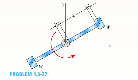
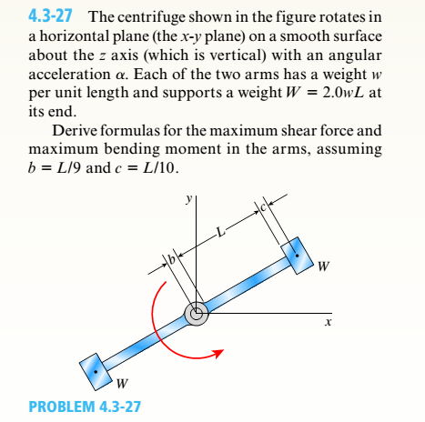
The centrifuge shown in the figure rotates in a horizontal plane (the x-y plane) on a smooth surface about the z axis (which is vertical) with an angular acceleration a. Each of the two arms has a weight w per unit length and supports a weight W = 2B/L at its end.
Derive formulas for the maximum shear force and maximum bending moment in the arms, assuming b = L/9 and c = L/10.
Expert Solution & Answer

Trending nowThis is a popular solution!

Students have asked these similar questions
!
Required information
An abrasive cutoff wheel has a diameter of 5 in, is 1/16 in thick, and has a 3/4-in bore. The wheel weighs 4.80 oz and
runs at 11,700 rev/min. The wheel material is isotropic, with a Poisson's ratio of 0.20, and has an ultimate strength of 12
kpsi.
Choose the correct equation from the following options:
Multiple Choice
о
σmax=
(314) (4r2 — r²)
-
о
σmax = p² (3+) (4r² + r²)
16
σmax =
(314) (4r² + r²)
σmax =
(314) (4² - r²)
I don't know how to solve this
I am not able to solve this question. Each part doesn't make sense to me.
Chapter 4 Solutions
Bundle: Mechanics Of Materials, Loose-leaf Version, 9th + Mindtap Engineering, 2 Terms (12 Months) Printed Access Card
Ch. 4 - Calculate the shear force V and bending moment...Ch. 4 - Determine the shear force V and bending moment M...Ch. 4 - Determine the shear force V and bending moment M...Ch. 4 - Calculate the shear force V and bending moment M...Ch. 4 - Consider the beam with an overhang shown in the...Ch. 4 - The beam ABC shown in the figure is simply...Ch. 4 - The beam ABCD shown in the figure has overhangs at...Ch. 4 - At a full d raw, an archer applies a pull of 130 N...Ch. 4 - A curved bar ABC is subjected to loads in the form...Ch. 4 - Under cruising conditions, the distributed load...
Ch. 4 - A beam ABCD with a vertical arm CE is supported as...Ch. 4 - A simply supported beam AB supports a trapezoid...Ch. 4 - Beam ABCD represents a reinforced-concrete...Ch. 4 - Find shear (V) and moment (M) at x = 3L/4 for the...Ch. 4 - Find expressions for shear force V and moment M at...Ch. 4 - Find expressions for shear force V and moment Mat...Ch. 4 - Find expressions for shear force V and moment Mat...Ch. 4 - Find expressions for shear force V and moment M at...Ch. 4 - Find expressions for shear force V and moment M at...Ch. 4 - Find expressions for shear force V and moment M at...Ch. 4 - A cable with force P is attached to a frame at A...Ch. 4 - Find expressions for shear force V and moment M at...Ch. 4 - A cable with force P is attached to a frame at D...Ch. 4 - Frame ABCD carries two concentrated loads (2P at T...Ch. 4 - Frame ABC has a moment release just left of joint...Ch. 4 - The simply supported beam ABCD is loaded by a...Ch. 4 - The centrifuge shown in the figure rotates in a...Ch. 4 - Draw the shear-Force and bending-moment diagrams...Ch. 4 - A simple beam AB is subjected to a counter...Ch. 4 - Draw the shear-force and bending-moment diagrams...Ch. 4 - The cantilever beam AB shown in the figure is...Ch. 4 - Cantilever beam AB carries an upward uniform load...Ch. 4 - The simple beam AB shown in the figure is...Ch. 4 - A simple beam AB subjected to couples M1and 3M2...Ch. 4 - A simply supported beam ABC is loaded by a...Ch. 4 - A simply supported beam ABC is loaded at the end...Ch. 4 - A beam ABC is simply supported at A and B and has...Ch. 4 - Beam ABCD is simply supported at B and C and has...Ch. 4 - Draw the shear-force and bending-moment diagrams...Ch. 4 - The simple beam AB supports a triangular load of...Ch. 4 - The beam AB shown in the figure supports a uniform...Ch. 4 - A cantilever beam AB supports a couple and a...Ch. 4 - The cantilever beam A B shown in the figure is...Ch. 4 - Beam ABC has simple supports at .A and B. an...Ch. 4 - Beam ABC with an overhang at one end supports a...Ch. 4 - Consider the two beams shown in the figures. Which...Ch. 4 - The three beams in the figure have the same...Ch. 4 - The beam ABC shown in the figure is simply...Ch. 4 - A simple beam AB is loaded by two segments of...Ch. 4 - Two beams (see figure) are loaded the same and...Ch. 4 - The beam A BCD shown in the figure has overhangs...Ch. 4 - A beam ABCD with a vertical arm CE is supported as...Ch. 4 - Beams ABC and CD are supported at A,C, and D and...Ch. 4 - The simple beam ACE shown in the figure is...Ch. 4 - A beam with simple supports is subjected to a...Ch. 4 - A beam of length L is designed to support a...Ch. 4 - The compound beam ABCDE shown in the figure...Ch. 4 - Draw the shear-force and bending-moment diagrams...Ch. 4 - The shear-force diagram for a simple beam is shown...Ch. 4 - The shear-force diagram for a beam is shown in the...Ch. 4 - A compound beam (see figure) has an internal...Ch. 4 - A compound beam (see figure) has an shear release...Ch. 4 - A simple beam AB supports two connected wheel...Ch. 4 - The inclined beam represents a ladder with the...Ch. 4 - Beam ABC is supported by a tie rod CD as shown....Ch. 4 - A plane frame (see figure) consists of column AB...Ch. 4 - The plane frame shown in the figure is part of an...
Knowledge Booster


Learn more about
Need a deep-dive on the concept behind this application? Look no further. Learn more about this topic, mechanical-engineering and related others by exploring similar questions and additional content below.Similar questions
- Exercises Find the solution of the following Differential Equations 1) y" + y = 3x² 3) "+2y+3y=27x 5) y"+y=6sin(x) 7) y"+4y+4y = 18 cosh(x) 9) (4)-5y"+4y = 10 cos(x) 11) y"+y=x²+x 13) y"-2y+y=e* 15) y+2y"-y'-2y=1-4x³ 2) y"+2y' + y = x² 4) "+y=-30 sin(4x) 6) y"+4y+3y=sin(x)+2 cos(x) 8) y"-2y+2y= 2e* cos(x) 10) y+y-2y=3e* 12) y"-y=e* 14) y"+y+y=x+4x³ +12x² 16) y"-2y+2y=2e* cos(x)arrow_forwardQu. 15 What are the indices for the Plane 1 drawn in the following sketch? Qu. 16 What are the Miller indices for the Plane shown in the following cubic unit cell? this is material engineering please show all workarrow_forwardI do not understand how to approach this question. I tried to answer it but I kept getting it incorrect.arrow_forward
- (read me)arrow_forward(read image)arrow_forwardQu. 13 What are the indices for the Direction 2 indicated by vector in the following sketch? Qu. 14 Determine the indices for the direction A and B shown in the following cubic unit cell. please show all work step by step from material engineeringarrow_forward
arrow_back_ios
SEE MORE QUESTIONS
arrow_forward_ios
Recommended textbooks for you
 Mechanics of Materials (MindTap Course List)Mechanical EngineeringISBN:9781337093347Author:Barry J. Goodno, James M. GerePublisher:Cengage Learning
Mechanics of Materials (MindTap Course List)
Mechanical Engineering
ISBN:9781337093347
Author:Barry J. Goodno, James M. Gere
Publisher:Cengage Learning
Understanding Shear Force and Bending Moment Diagrams; Author: The Efficient Engineer;https://www.youtube.com/watch?v=C-FEVzI8oe8;License: Standard YouTube License, CC-BY
Bending Stress; Author: moodlemech;https://www.youtube.com/watch?v=9QIqewkE6xM;License: Standard Youtube License