Design of Machinery
6th Edition
ISBN: 9781260431315
Author: Norton, Robert
Publisher: MCGRAW-HILL HIGHER EDUCATION
expand_more
expand_more
format_list_bulleted
Videos
Textbook Question
Chapter 4, Problem 4.12P
Repeat Problem 4-11 except solve by the 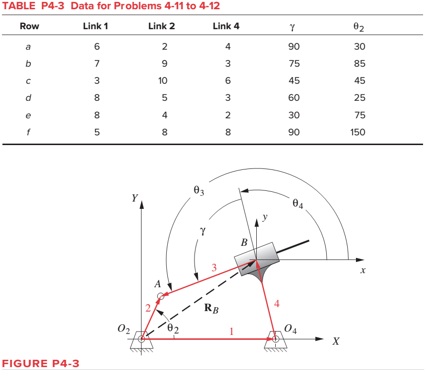
Expert Solution & Answer

Trending nowThis is a popular solution!

Students have asked these similar questions
3. Find a basis of solutions by the Frobenius method. Try to identify the series as expansions of
known functions.
8x2y" +10xy' + (x 1)y = 0
-
Hello I was going over the solution for this probem and I'm a bit confused on the last part. Can you please explain to me 1^4 was used for the Co of the tubular cross section? Thank you!
Blood (HD = 0.45 in large diameter tubes) is forced through hollow fiber tubes that are 20 µm in diameter.Equating the volumetric flowrate expressions from (1) assuming marginal zone theory and (2) using an apparentviscosity for the blood, estimate the marginal zone thickness at this diameter. The viscosity of plasma is 1.2 cP
Chapter 4 Solutions
Design of Machinery
Ch. 4 - A position vector is defined as having a length...Ch. 4 - A particle is traveling along an arc of 6.5-in...Ch. 4 - Repeat problem 4-2 considering points A and B to...Ch. 4 - Repeat Problem 4-2 with the particles path defined...Ch. 4 - Repeat Problem 4-3 with the path of the particle...Ch. 4 - The link lengths and the value of 2 for some...Ch. 4 - Repeat Problem 4-6 except solve by the vector loop...Ch. 4 - Expand equation 4.7b and prove that it reduces to...Ch. 4 - The link lengths and the value of 2 and offset for...Ch. 4 - Repeat Problem 4-9 except solve by the vector loop...
Ch. 4 - The link lengths and the value of 2 and for some...Ch. 4 - Repeat Problem 4-11 except solve by the vector...Ch. 4 - Find the transmission angles of the linkages in...Ch. 4 - Find the minimum and maximum values of the...Ch. 4 - Find the input angles corresponding to the toggle...Ch. 4 - The link lengths. gear ratio (). phase angle (),...Ch. 4 - Repeat Problem 4-16 except solve by the vector...Ch. 4 - Figure P4-5 shows the mechanisms for the following...Ch. 4 - For one revolution of driving link 2 of the...Ch. 4 - Figure P4-7 shows a power hacksaw, used to cut...Ch. 4 - For the linkage in Figure P4-8, find its limit...Ch. 4 - For the walking-beam mechanism of Figure P4-9,...Ch. 4 - For the linkage in Figure P4-10, calculate and...Ch. 4 - For the linkage in Figure P4-11, calculate and...Ch. 4 - For the linkage in Figure P4-12, find its limit...Ch. 4 - Prob. 4.26PCh. 4 - For the linkage in Figure P4-13, find its limit...Ch. 4 - Prob. 4.28PCh. 4 - For the linkage in Figure P4-15, find its limit...Ch. 4 - For the linkage in Figure P4-15, find its limit...Ch. 4 - Prob. 4.31PCh. 4 - Prob. 4.32PCh. 4 - Figure 4-22 plots the cubic function from equation...Ch. 4 - Write a computer program or use an equation solver...Ch. 4 - Prob. 4.35PCh. 4 - Prob. 4.36PCh. 4 - Write a computer program or use an equation solver...Ch. 4 - Write a computer program or use an equation solver...Ch. 4 - Prob. 4.39PCh. 4 - Prob. 4.40PCh. 4 - Write a computer program or use an equation solver...Ch. 4 - Prob. 4.42PCh. 4 - Prob. 4.43PCh. 4 - Prob. 4.44PCh. 4 - Model the linkage shown in Figure 3-37a in...Ch. 4 - Prob. 4.46PCh. 4 - Prob. 4.47PCh. 4 - Prob. 4.48PCh. 4 - Prob. 4.49PCh. 4 - Prob. 4.50PCh. 4 - Figure 3-29g shows Evans approximate straight-line...Ch. 4 - For the linkage in Figure P4-16, what are the...Ch. 4 - The coordinates of the point P1 on link 4 in...Ch. 4 - Write a computer program or use an equation solver...Ch. 4 - For the linkage in Figure P4-17, calculate the...Ch. 4 - Prob. 4.56PCh. 4 - Prob. 4.57PCh. 4 - The elliptical trammel in Figure P4-18 must be...Ch. 4 - Prob. 4.59PCh. 4 - Prob. 4.60PCh. 4 - Repeat Problem 4-60 except solve by the vector...Ch. 4 - Write a computer program or use an equation solver...Ch. 4 - Write a computer program or use an equation solver...Ch. 4 - Write a computer program or use an equation solver...Ch. 4 - Write a computer program or use an equation solver...Ch. 4 - Figure P4-20 shows a cut-away view of a mechanism...Ch. 4 - For the linkage in Figure 3-32a, calculate and...
Additional Engineering Textbook Solutions
Find more solutions based on key concepts
What types of coolant are used in vehicles?
Automotive Technology: Principles, Diagnosis, And Service (6th Edition) (halderman Automotive Series)
The solid steel shaft AC has a diameter of 25 mm and is supported by smooth bearings at D and E. It is coupled ...
Mechanics of Materials (10th Edition)
This optional Google account security feature sends you a message with a code that you must enter, in addition ...
SURVEY OF OPERATING SYSTEMS
How is the hydrodynamic entry length defined for flow in a pipe? Is the entry length longer in laminar or turbu...
Fluid Mechanics: Fundamentals and Applications
CONCEPT QUESTIONS
15.CQ3 The ball rolls without slipping on the fixed surface as shown. What is the direction ...
Vector Mechanics for Engineers: Statics and Dynamics
1.2 Explain the difference between geodetic and plane
surveys,
Elementary Surveying: An Introduction To Geomatics (15th Edition)
Knowledge Booster


Learn more about
Need a deep-dive on the concept behind this application? Look no further. Learn more about this topic, mechanical-engineering and related others by exploring similar questions and additional content below.Similar questions
- Q2: Find the shear load on bolt A for the connection shown in Figure 2. Dimensions are in mm Fig. 2 24 0-0 0-0 A 180kN (10 Markarrow_forwarddetermine the direction and magnitude of angular velocity ω3 of link CD in the four-bar linkage using the relative velocity graphical methodarrow_forwardFour-bar linkage mechanism, AB=40mm, BC=60mm, CD=70mm, AD=80mm, =60°, w1=10rad/s. Determine the direction and magnitude of w3 using relative motion graphical method. A B 2 3 77777 477777arrow_forward
- Four-bar linkage mechanism, AB=40mm, BC=60mm, CD=70mm, AD=80mm, =60°, w1=10rad/s. Determine the direction and magnitude of w3 using relative motion graphical method. A B 2 3 77777 477777arrow_forwardThe evaporator of a vapor compression refrigeration cycle utilizing R-123 as the refrigerant isbeing used to chill water. The evaporator is a shell and tube heat exchanger with the water flowingthrough the tubes. The water enters the heat exchanger at a temperature of 54°F. The approachtemperature difference of the evaporator is 3°R. The evaporating pressure of the refrigeration cycleis 4.8 psia and the condensing pressure is 75 psia. The refrigerant is flowing through the cycle witha flow rate of 18,000 lbm/hr. The R-123 leaves the evaporator as a saturated vapor and leaves thecondenser as a saturated liquid. Determine the following:a. The outlet temperature of the chilled waterb. The volumetric flow rate of the chilled water (gpm)c. The UA product of the evaporator (Btu/h-°F)d. The heat transfer rate between the refrigerant and the water (tons)arrow_forward(Read image) (Answer given)arrow_forward
- Problem (17): water flowing in an open channel of a rectangular cross-section with width (b) transitions from a mild slope to a steep slope (i.e., from subcritical to supercritical flow) with normal water depths of (y₁) and (y2), respectively. Given the values of y₁ [m], y₂ [m], and b [m], calculate the discharge in the channel (Q) in [Lit/s]. Givens: y1 = 4.112 m y2 = 0.387 m b = 0.942 m Answers: ( 1 ) 1880.186 lit/s ( 2 ) 4042.945 lit/s ( 3 ) 2553.11 lit/s ( 4 ) 3130.448 lit/sarrow_forwardProblem (14): A pump is being used to lift water from an underground tank through a pipe of diameter (d) at discharge (Q). The total head loss until the pump entrance can be calculated as (h₁ = K[V²/2g]), h where (V) is the flow velocity in the pipe. The elevation difference between the pump and tank surface is (h). Given the values of h [cm], d [cm], and K [-], calculate the maximum discharge Q [Lit/s] beyond which cavitation would take place at the pump entrance. Assume Turbulent flow conditions. Givens: h = 120.31 cm d = 14.455 cm K = 8.976 Q Answers: (1) 94.917 lit/s (2) 49.048 lit/s ( 3 ) 80.722 lit/s 68.588 lit/s 4arrow_forwardProblem (13): A pump is being used to lift water from the bottom tank to the top tank in a galvanized iron pipe at a discharge (Q). The length and diameter of the pipe section from the bottom tank to the pump are (L₁) and (d₁), respectively. The length and diameter of the pipe section from the pump to the top tank are (L2) and (d2), respectively. Given the values of Q [L/s], L₁ [m], d₁ [m], L₂ [m], d₂ [m], calculate total head loss due to friction (i.e., major loss) in the pipe (hmajor-loss) in [cm]. Givens: L₁,d₁ Pump L₂,d2 오 0.533 lit/s L1 = 6920.729 m d1 = 1.065 m L2 = 70.946 m d2 0.072 m Answers: (1) 3.069 cm (2) 3.914 cm ( 3 ) 2.519 cm ( 4 ) 1.855 cm TABLE 8.1 Equivalent Roughness for New Pipes Pipe Riveted steel Concrete Wood stave Cast iron Galvanized iron Equivalent Roughness, & Feet Millimeters 0.003-0.03 0.9-9.0 0.001-0.01 0.3-3.0 0.0006-0.003 0.18-0.9 0.00085 0.26 0.0005 0.15 0.045 0.000005 0.0015 0.0 (smooth) 0.0 (smooth) Commercial steel or wrought iron 0.00015 Drawn…arrow_forward
- The flow rate is 12.275 Liters/s and the diameter is 6.266 cm.arrow_forwardAn experimental setup is being built to study the flow in a large water main (i.e., a large pipe). The water main is expected to convey a discharge (Qp). The experimental tube will be built at a length scale of 1/20 of the actual water main. After building the experimental setup, the pressure drop per unit length in the model tube (APm/Lm) is measured. Problem (20): Given the value of APm/Lm [kPa/m], and assuming pressure coefficient similitude, calculate the drop in the pressure per unit length of the water main (APP/Lp) in [Pa/m]. Givens: AP M/L m = 590.637 kPa/m meen Answers: ( 1 ) 59.369 Pa/m ( 2 ) 73.83 Pa/m (3) 95.443 Pa/m ( 4 ) 44.444 Pa/m *******arrow_forwardFind the reaction force in y if Ain = 0.169 m^2, Aout = 0.143 m^2, p_in = 0.552 atm, Q = 0.367 m^3/s, α = 31.72 degrees. The pipe is flat on the ground so do not factor in weight of the pipe and fluid.arrow_forward
arrow_back_ios
SEE MORE QUESTIONS
arrow_forward_ios
Recommended textbooks for you
 Elements Of ElectromagneticsMechanical EngineeringISBN:9780190698614Author:Sadiku, Matthew N. O.Publisher:Oxford University Press
 Mechanics of Materials (10th Edition)Mechanical EngineeringISBN:9780134319650Author:Russell C. HibbelerPublisher:PEARSON
 Thermodynamics: An Engineering ApproachMechanical EngineeringISBN:9781259822674Author:Yunus A. Cengel Dr., Michael A. BolesPublisher:McGraw-Hill Education
 Control Systems EngineeringMechanical EngineeringISBN:9781118170519Author:Norman S. NisePublisher:WILEY
 Mechanics of Materials (MindTap Course List)Mechanical EngineeringISBN:9781337093347Author:Barry J. Goodno, James M. GerePublisher:Cengage Learning
 Engineering Mechanics: StaticsMechanical EngineeringISBN:9781118807330Author:James L. Meriam, L. G. Kraige, J. N. BoltonPublisher:WILEY
Elements Of Electromagnetics
Mechanical Engineering
ISBN:9780190698614
Author:Sadiku, Matthew N. O.
Publisher:Oxford University Press
Mechanics of Materials (10th Edition)
Mechanical Engineering
ISBN:9780134319650
Author:Russell C. Hibbeler
Publisher:PEARSON
Thermodynamics: An Engineering Approach
Mechanical Engineering
ISBN:9781259822674
Author:Yunus A. Cengel Dr., Michael A. Boles
Publisher:McGraw-Hill Education
Control Systems Engineering
Mechanical Engineering
ISBN:9781118170519
Author:Norman S. Nise
Publisher:WILEY
Mechanics of Materials (MindTap Course List)
Mechanical Engineering
ISBN:9781337093347
Author:Barry J. Goodno, James M. Gere
Publisher:Cengage Learning
Engineering Mechanics: Statics
Mechanical Engineering
ISBN:9781118807330
Author:James L. Meriam, L. G. Kraige, J. N. Bolton
Publisher:WILEY
Polymer Basics; Author: Tonya Coffey;https://www.youtube.com/watch?v=c5gFHpWvDXk;License: Standard youtube license