
Electric Motor Control
10th Edition
ISBN: 9781133702818
Author: Herman
Publisher: CENGAGE L
expand_more
expand_more
format_list_bulleted
Videos
Textbook Question
Chapter 4, Problem 1SQ
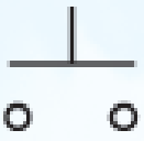
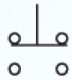
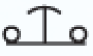
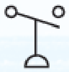
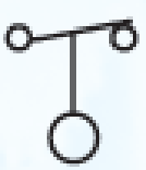
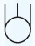
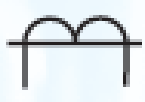
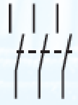
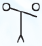
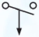
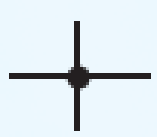
Identify the following symbols.


Expert Solution & Answer
To determine
Identify the given symbols.
Explanation of Solution
Discussion:
The names of the symbols are provided in Table 1.
Table 1
| Part | Name of the symbol | Description |
| a. | Normally open, momentary contact push button. | It is a type of push button, through which two contacts are closed or opened at a time. |
| b. | Double-acting, momentary contact push button. | It is a type of push button, through which two operations can be performed using single push button. |
| c. | Mushroom head, normally closed, momentary contact push button. | It is a palm operated push button. |
| d. | Normally open pressure switch. | It is a type of pressure control relay. |
| e. | Normally closed float switch. | It is a type of pilot devices. It controls the circuit through single contact. |
| f. | Three-phase squirrel cage motor. | It is a type of motor. |
| g. | Current transformer. | It is a type of transformer that is mostly used in large motor starters to step down the current. |
| h. | Three-phase disconnect switch. | It is a type of switch that is used to disconnect the three phases from supply. |
| i. | Normally open contact. | It is a type of switch, in which no current flows in the circuit. |
| j. | Normally open, on-delay timer contact. | It is a type of timed contacts. |
| k. | Normally open, off-delay timer contact. | It is a type of timed contacts. |
| l. | Normally open limit switch. | It is a type of limit switch. |
| m. | Node point showing connected conductors. | It is a point at which two or more conductors are connected. |
| n. | Red pilot light. | It is mostly used for the indication of pilot lights. |
| o. | Normally open switch (single-pole single-throw switch). | It is a type of switch. By single throw, the switch can be either opened or closed. |
| p. | Double-break switch. | It is a type of switch, in which two contacts are to be opened or closed at a time. |
Conclusion:
Thus, the names for the given symbols are provided.
Want to see more full solutions like this?
Subscribe now to access step-by-step solutions to millions of textbook problems written by subject matter experts!
Students have asked these similar questions
Choose the correct answer for from the following sentences:
1. The purpose of the microprocessor is to control
b. memory
c. processing
d. tasks
a. switches
2. Which of the following instructions represents base-plus-index addressing mode?
a. MOV AL,[BX] b. MOV AL,[SI] c. MOV AL,BX d. MOV AL,[BX+SI]
3. The BIU pre-fetches the instruction from memory and store them in
b. memory
c. stack
d. queue
a. register
4. Which function is used to control the PWM (Pulse Width Modulation) on the Arduino
output pin?
a. digitalRead() b. analogRead() c. digitalWrite()
5. Which port in the PIC16F877A has an 8 external interrupt inputs?
a. Port-A
b. Port-C
c. Port-B
d. analogWrite()
d. Port-D
d. 4KByte
6. How much Flash EEPROM memory program found in the PIC16F877A microcontroller?
a. 32KByte
b. 16KByte
c. 8KByte
Solve and select the correct answer:
2. For a random variable X with pdf: p(x)
value of x is
=
119
10
for -5≤x≤5. The mean
(a) -75
(b) 10
(c) 0
(d) 75
3. Is the matrix A = = [1] orthogonal? Find the rank of A?
0
(a) YES, -1
(b) NO, 2
(c) YES, 2
(d) NO, -1
4. L{et sin(3t)u(t)) = (a)
s-3
(s-2)²+9
2
(b)
(5-3)² (c)
(s-3)²+4
S-2
3
(s-2)²+9
(d) (5-2)²+9
=
5. Given that x is a constant. Choose all the correct solutions for [∞ (AB)] =
(a) (AB)T (b) x ATBT
(c) α BTAT
(d) x (AB)T
DO NOT WANT AI WILL REJECT
Chapter 4 Solutions
Electric Motor Control
Ch. 4 - Identify the following symbols.Ch. 4 - Electrical symbols usually conform to which...Ch. 4 - What do the following abbreviations stand for? a....Ch. 4 - Single-pole and double-pole switch symbols are...Ch. 4 - The symbol shown is a a. polarized capacitor. b....Ch. 4 - The symbol shown is a a. normally closed float...Ch. 4 - The symbol shown is a(n) a. iron core transformer....Ch. 4 - The symbol shown is a a. normally open pressure...Ch. 4 - The symbol shown is a a. double-acting push...Ch. 4 - If you were installing the circuit in Figure 412,...
Knowledge Booster


Learn more about
Need a deep-dive on the concept behind this application? Look no further. Learn more about this topic, electrical-engineering and related others by exploring similar questions and additional content below.Similar questions
- 3. Roughly sketch the root locus for the following locations of open-loop poles and zeros. You just need to show the shape of the root locus; you do not calculate the asymptote, break-in, and break-away points. ☑ (a) (b) ☑ Φ ① $3 (c)arrow_forwardDO NOT WANT AI WILL REJECTarrow_forwardDO NOT NEED AI WILL REJECTarrow_forward
- S+4 4. Sketch the root locus for L(s) = (s+6) (s+1)2 using rules 1, 2, and 3. For rule 3, you need to find the value of σ and a for the asymptotes. From the root-locus, explain why the closed-loop system is always stable for any choice of the design parameter K in the range 0 < K < ∞o.arrow_forward2. Consider the following system. K(s+3) (s+4) (s+1)(s+2) Check whether the points below are in the root locus. If the point is in the root locus, then also find what the corresponding gain K. i) ii) -2+j3 -2+1√ √ Hint: First find L(s). Next, in L(s) replace s with the value of the point and then express it in polar format r20 using calculator. The point will be in the root locus if and only if = 180° or odd multiple of 180°. When the point is in the root locus, the corresponding gain K is obtained as K ==arrow_forwardsolve and show workarrow_forward
- Design and find values. please solve ASAP (it's for practice before an exma, I don't have time)arrow_forwardCan you show why the answer is that for this question using second order differential equations, instead of laplace transformsarrow_forward2. For each of the following transfer functions, G(s) = Y(s)/U(s), find the differential equation relating the input u(t) to the output y(t). (s+2)(s+3) (a) G(s) = (s+1)(s+4) (s²+0.4s+1.04) (s+3) (b) G(s)= (s2+0.2s+1)(s+2)(s+4)arrow_forward
arrow_back_ios
SEE MORE QUESTIONS
arrow_forward_ios
Recommended textbooks for you

 Electricity for Refrigeration, Heating, and Air C...Mechanical EngineeringISBN:9781337399128Author:Russell E. SmithPublisher:Cengage Learning
 EBK ELECTRICAL WIRING RESIDENTIALElectrical EngineeringISBN:9781337516549Author:SimmonsPublisher:CENGAGE LEARNING - CONSIGNMENT
 Delmar's Standard Textbook Of ElectricityElectrical EngineeringISBN:9781337900348Author:Stephen L. HermanPublisher:Cengage Learning
Electricity for Refrigeration, Heating, and Air C...
Mechanical Engineering
ISBN:9781337399128
Author:Russell E. Smith
Publisher:Cengage Learning
EBK ELECTRICAL WIRING RESIDENTIAL
Electrical Engineering
ISBN:9781337516549
Author:Simmons
Publisher:CENGAGE LEARNING - CONSIGNMENT
Delmar's Standard Textbook Of Electricity
Electrical Engineering
ISBN:9781337900348
Author:Stephen L. Herman
Publisher:Cengage Learning
Digital modulation: ASK, FSK, and PSK; Author: Sunny Classroom;https://www.youtube.com/watch?v=qGwUOvErR8Q;License: Standard Youtube License