
Concept explainers
Videos
(a)
Calculate the number of branches in the circuit.
(a)
Answer to Problem 1P
The number of branches in the circuit is 12 branches.
Explanation of Solution
Given data:
Refer to Figure P4.1 in the textbook.
The given circuit is modified as shown in Figure 1.
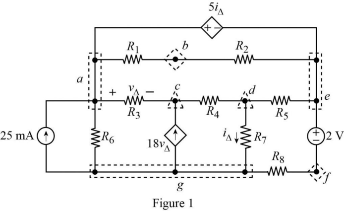
A branch is defined as a single electrical device or elements.
In Figure 1, there are 12 branches in the circuit. They are,
That is, 2 branch with a dependent source, 2 branches with independent sources, and 8 branches with resistors.
Conclusion:
Thus, the number of branches in the circuit is 12 branches.
(b)
Find the number of branches where the current is unknown.
(b)
Answer to Problem 1P
The number of branches in which the current unknown is 11 branches.
Explanation of Solution
Given data:
Refer to Figure 1 in Part (a).
In Figure 1, the only one known current in the circuit which is the
Conclusion:
Thus, the number of branches in which the current unknown is 11 branches.
(c)
Find the number of essential branches in the circuit.
(c)
Answer to Problem 1P
The number of essential branches in the circuit is 10 essential branches.
Explanation of Solution
Given data:
Refer to Figure 1 in Part (a).
Essential branch: It is defined as a path that attaches essential nodes without passing through an essential node.
The essential branches in the circuit are,
In the circuit,
Therefore, the circuit has 10 essential branches.
Conclusion:
Thus, the number of essential branches in the circuit is 10 essential branches.
(d)
Find the number of essential branches where the current is unknown in the circuit.
(d)
Answer to Problem 1P
The number of essential branches where the current unknown is 9 essential branches.
Explanation of Solution
Given data:
Refer to Figure 1 in Part (a).
Refer to Part (c), the circuit has 10 essential branches.
In Figure 1, the current is known only in the essential branch that containing the
Therefore, in 9 essential branches the current is unknown.
Conclusion:
Thus, the number of essential branches where the current unknown is 9 essential branches.
(e)
Find the number of nodes in the circuit.
(e)
Answer to Problem 1P
The number of nodes in the circuit is 7 nodes.
Explanation of Solution
Given data:
Refer to Figure 1 in Part (a).
Node: It is defined as a connection point between two or more branches.
In Figure 1, the nodes present in the circuit are,
Conclusion:
Thus, the number of nodes in the circuit is 7 nodes.
(f)
Find the number of essential nodes in the circuit.
(f)
Answer to Problem 1P
The number of essential nodes in the circuit is 5 essential nodes.
Explanation of Solution
Given data:
Refer to Figure 1 in Part (a).
Essential node: It is a node that joins three or more electrical element or devices
In Figure 1, the essential nodes present in the circuit are
Conclusion:
Thus, the number of essential nodes present in the circuit is 5 essential nodes.
(g)
Find the number of meshes present in the circuit.
(g)
Answer to Problem 1P
The number of meshes present in the circuit is 6 meshes.
Explanation of Solution
Given data:
Refer to Figure 1 in Part (a).
Mesh: It is defined as a closed loop path that has no any other smaller loops present inside.
In Figure 1, the closed loops present in the circuit are
Conclusion:
Thus, the number of meshes present in the circuit is 6 meshes.
Want to see more full solutions like this?
Chapter 4 Solutions
Electric Circuits (10th Edition)
Additional Engineering Textbook Solutions
Starting Out with C++ from Control Structures to Objects (9th Edition)
Starting Out with Python (4th Edition)
Starting Out with Java: From Control Structures through Objects (7th Edition) (What's New in Computer Science)
Starting Out With Visual Basic (8th Edition)
Web Development and Design Foundations with HTML5 (8th Edition)
INTERNATIONAL EDITION---Engineering Mechanics: Statics, 14th edition (SI unit)


- Many machines, such as lathes, milling machines, and grinders, are equipped with tracers to reproduce the contours of templates. The figure is a schematic diagram of a hydraulic tracer in which the tool duplicates the shape of the template on the workpiece. a) Explain how the system works. b) Draw a block diagram and identify the system's elements. c) Classify the control system. Oil under pressure Template Style Tool Piece of workarrow_forward2. Refrigerators to maintain the product at a given temperature have a control system. a) Explain how the control system is or how you think it should be (Make a diagram). b) Make the typical block diagram of a control system and identify the components in the refrigerator system. c) Classify the control system.arrow_forward3. Internal combustion engines require a cooling system to function properly, which maintains the engine temperature at an appropriate value. Neither too high nor too low. There are several systems to control this temperature, the two best known are: • The classic one that uses a thermostat that regulates the flow of coolant (water), and where the fan is mechanically coupled to the engine. • In more recent vehicles, in addition to the thermostat, a temperature controller is used that turns an electric fan on and off. Select one of the two systems mentioned above and: a) Explain how it works, using diagrams. b) Make the typical block diagram of a feedback control system, identifying the components of the system. c) Classify the control system.arrow_forward
- A 3-phase, star connected, 10 kVA, 380 V, salient pole alternator with direct and quadrature axis reactances of 15 and 8 0/ph respectively, delivers full-load current at 0.8 power factor lagging. Neglect the armature resistance. Determine the following: (a) The load angle, (b) The direct axis and quadrature axis components of armature current, (c) E.M.F induced voltage of the alternator, (d) The voltage regulation, and (e) The developed power by the alternator?arrow_forwardA 2000 kVA,Y- connected alternator gives an open circuit line voltage of 3.3 kV for a field current of 65 A. For same field current the short circuit current is being equal to full load current. Calculate the full load voltage regulation at both 0.8 lagging p.f. and unity p.f., neglect armature resistance?arrow_forwardDon't use ai to answer I will report you answerarrow_forward
 Introductory Circuit Analysis (13th Edition)Electrical EngineeringISBN:9780133923605Author:Robert L. BoylestadPublisher:PEARSON
 Delmar's Standard Textbook Of ElectricityElectrical EngineeringISBN:9781337900348Author:Stephen L. HermanPublisher:Cengage Learning
 Programmable Logic ControllersElectrical EngineeringISBN:9780073373843Author:Frank D. PetruzellaPublisher:McGraw-Hill Education
 Fundamentals of Electric CircuitsElectrical EngineeringISBN:9780078028229Author:Charles K Alexander, Matthew SadikuPublisher:McGraw-Hill Education
 Electric Circuits. (11th Edition)Electrical EngineeringISBN:9780134746968Author:James W. Nilsson, Susan RiedelPublisher:PEARSON
 Engineering ElectromagneticsElectrical EngineeringISBN:9780078028151Author:Hayt, William H. (william Hart), Jr, BUCK, John A.Publisher:Mcgraw-hill Education,