Three network topologies, four different network types, along withthe uses and limitations of each.
Explanation of Solution
Network topologies defines the shape, structure and arrangement in which components of a network can be linked. Though, among networks transmission rate, distance between nodes, signal types and physical media uses for connection may differ, but they may have the same topology.
The three main popular network topologies used are star, bus and mesh topologies.
Star topology: In this topology, all nodes in a network are connected to a central node which is known as hub node. Start topology is very easy to implement and is used when lesser number of devices are required to be connected. The main drawback of star topology is that in case, there is failure of central node, the entire network will go down. The figure below shows devices connected in star topology:

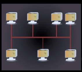
Bus topology: In this topology, every node on the network is connected through a common commnication channel known as Bus. For communication purposes, whenever any device needs to communicate with any other device, it sends braodcast messages through a communication link which goes to all devices but can only be accepted and processed by the intended receiving device. But topology is the easiest way to establishing a network and also,the cost of implementation is less. The main issue with bus topology is that for a large network, there is more amount of time needed for communication between devices at extreme ends than devices which are in close proximity. Also, in case of failure of bus, the whole network has to be restructured which is a very time consuming process. The following figure shows bus topology:
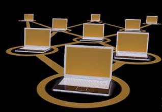
Mesh topology: In mesh topology, nodes can be connected on network using multiple access points. Each device on the network is directly linked with another device. In mesh topology, a connection is established between the sending device and receiving device by routing through node to node and make a continous connection which does not have any blocked nodes. Mesh topology is the most reliable type of
Based on physical distances between the connected nodes of a network, the networkscan be classified as personal area network, local area network, metropolitan area network and wide area network.
Personal area network (PAN): PAN is a wireless network which is setup near a person. A person can connect laptops, digital cameras, mobile phones, printers etc by using personal area. all together. PAN is also used in IoT connections for allowing sensors to receive data from your body and transmit it to your smartphone which can be used for health tracking, glucose monitoring, and pedometers.
Local area network (LAN): LAN network connects computing devices within an office, home or building. Typically, a LAN network, has hundreds of computing devices connected to the network. LAN network is used to create a private and secure network.
Metropolitan area network (MAN): MAN is used to connect multiple LAN networks spread across various small geographical locations together. Two or more LAN networks can be connected into a WAN network. MAN, networks can be used to connect multiple offices of an organization locatedin different locations.
Wide area network (WAN): WAN is used to connect large geographical regions. They are mainly used to provide communication over national borders. A WAN network can be either be privately owned or can be rented. WAN comes to picture when you try to make a phone call to somebody who is in any other international location. For establishing WAN, national and international laws need to be taken care while handling and monitoring data flow through these networks.
Want to see more full solutions like this?
Chapter 4 Solutions
Fundamentals of Information Systems (Looseleaf)

- Just need some assistance with number 3 please, in C#arrow_forwardHow do we find the possible final values of variable x in the following program. Int x=0; sem s1=1, s2 =0; CO P(s2); P(s1); x=x*2; V(s1); // P(s1); x=x*x; V(s1); // P(s1); x=x+3; V(s2); V(s1); Ocarrow_forwardLab 07: Java Graphics (Bonus lab) In this lab, we'll be practicing what we learned about GUIs, and Mouse events. You will need to implement the following: ➤ A GUI with a drawing panel. We can click in this panel, and you will capture those clicks as a Point (see java.awt.Point) in a PointCollection class (you need to build this). о The points need to be represented by circles. Below the drawing panel, you will need 5 buttons: о An input button to register your mouse to the drawing panel. ○ о о A show button to paint the points in your collection on the drawing panel. A button to shift all the points to the left by 50 pixels. The x position of the points is not allowed to go below zero. Another button to shift all the points to the right 50 pixels. The x position of the points cannot go further than the You can implement this GUI in any way you choose. I suggest using the BorderLayout for a panel containing the buttons, and a GridLayout to hold the drawing panel and button panels.…arrow_forward
- If a UDP datagram is sent from host A, port P to host B, port Q, but at host B there is no process listening to port Q, then B is to send back an ICMP Port Unreachable message to A. Like all ICMP messages, this is addressed to A as a whole, not to port P on A. (a) Give an example of when an application might want to receive such ICMP messages. (b) Find out what an application has to do, on the operating system of your choice, to receive such messages. (c) Why might it not be a good idea to send such messages directly back to the originating port P on A?arrow_forwardDiscuss how business intelligence and data visualization work together to help decision-makers and data users. Provide 2 specific use cases.arrow_forwardThis week we will be building a regression model conceptually for our discussion assignment. Consider your current workplace (or previous/future workplace if not currently working) and answer the following set of questions. Expand where needed to help others understand your thinking: What is the most important factor (variable) that needs to be predicted accurately at work? Why? Justify its selection as your dependent variable.arrow_forward
- According to best practices, you should always make a copy of a config file and add a date to filename before editing? Explain why this should be done and what could be the pitfalls of not doing it.arrow_forwardIn completing this report, you may be required to rely heavily on principles relevant, for example, the Work System, Managerial and Functional Levels, Information and International Systems, and Security. apply Problem Solving Techniques (Think Outside The Box) when completing. should reflect relevance, clarity, and organisation based on research. Your research must be demonstrated by Details from the scenario to support your analysis, Theories from your readings, Three or more scholarly references are required from books, UWIlinc, etc, in-text or narrated citations of at least four (4) references. “Implementation of an Integrated Inventory Management System at Green Fields Manufacturing” Green Fields Manufacturing is a mid-sized company specialising in eco-friendly home and garden products. In recent years, growing demand has exposed the limitations of their fragmented processes and outdated systems. Different departments manage production schedules, raw material requirements, and…arrow_forward1. Create a Book record that implements the Comparable interface, comparing the Book objects by year - title: String > - author: String - year: int Book + compareTo(other Book: Book): int + toString(): String Submit your source code on Canvas (Copy your code to text box or upload.java file) > Comparable 2. Create a main method in Book record. 1) In the main method, create an array of 2 objects of Book with your choice of title, author, and year. 2) Sort the array by year 3) Print the object. Override the toString in Book to match the example output: @Javadoc Declaration Console X Properties Book [Java Application] /Users/kuan/.p2/pool/plugins/org.eclipse.justj.openjdk.hotspo [Book: year=1901, Book: year=2010]arrow_forward
- Q5-The efficiency of a 200 KVA, single phase transformer is 98% when operating at full load 0.8 lagging p.f. the iron losses in the transformer is 2000 watt. Calculate the i) Full load copper losses ii) half load copper losses and efficiency at half load. Ans: 1265.306 watt, 97.186%arrow_forward2. Consider the following pseudocode for partition: function partition (A,L,R) pivotkey = A [R] t = L for i L to R-1 inclusive: if A[i] A[i] t = t + 1 end if end for A [t] A[R] return t end function Suppose we call partition (A,0,5) on A=[10,1,9,2,8,5]. Show the state of the list at the indicated instances. Initial A After i=0 ends After 1 ends After i 2 ends After i = 3 ends After i = 4 ends After final swap 10 19 285 [12 pts]arrow_forward.NET Interactive Solving Sudoku using Grover's Algorithm We will now solve a simple problem using Grover's algorithm, for which we do not necessarily know the solution beforehand. Our problem is a 2x2 binary sudoku, which in our case has two simple rules: •No column may contain the same value twice •No row may contain the same value twice If we assign each square in our sudoku to a variable like so: 1 V V₁ V3 V2 we want our circuit to output a solution to this sudoku. Note that, while this approach of using Grover's algorithm to solve this problem is not practical (you can probably find the solution in your head!), the purpose of this example is to demonstrate the conversion of classical decision problems into oracles for Grover's algorithm. Turning the Problem into a Circuit We want to create an oracle that will help us solve this problem, and we will start by creating a circuit that identifies a correct solution, we simply need to create a classical function on a quantum circuit that…arrow_forward
 Fundamentals of Information SystemsComputer ScienceISBN:9781337097536Author:Ralph Stair, George ReynoldsPublisher:Cengage Learning
 Fundamentals of Information SystemsComputer ScienceISBN:9781305082168Author:Ralph Stair, George ReynoldsPublisher:Cengage Learning
 Management Of Information SecurityComputer ScienceISBN:9781337405713Author:WHITMAN, Michael.Publisher:Cengage Learning,
 Principles of Information Systems (MindTap Course...Computer ScienceISBN:9781285867168Author:Ralph Stair, George ReynoldsPublisher:Cengage Learning
 Principles of Information Systems (MindTap Course...Computer ScienceISBN:9781305971776Author:Ralph Stair, George ReynoldsPublisher:Cengage Learning