
Concept explainers
Find the forces in the members of the truss by the method of joints.
Explanation of Solution
Given information:
Apply the sign conventions for calculating reactions, forces and moments using the three equations of equilibrium as shown below.
- For summation of forces along x-direction is equal to zero
- For summation of forces along y-direction is equal to zero
- For summation of moment about a point is equal to zero
Method of joints:
The negative value of force in any member indicates compression (C) and the positive value of force in any member indicates Tension (T).
Calculation:
Consider the forces in the members AB, BC, CD, DE, EF, FG, AH, HI, IJ, JK, KL, LG, BH, CI, DJ, EK, FL, CH, DI, DK, and EL are
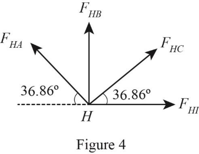
Show the free body diagram of the truss as shown in Figure 1.
Refer Figure 1.
Consider the horizontal and vertical reactions at A are
Consider the vertical reaction at G is
Calculate the value of the angle
Take the sum of the forces in the vertical direction as zero.
Take the sum of the forces in the horizontal direction as zero.
Take the sum of the moments at A is zero. Then,
Substitute
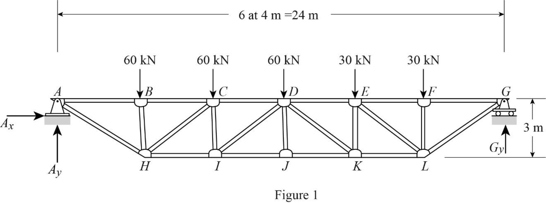
Show the joint A as shown in Figure 2.
Refer Figure 2.
Find the forces in the member AH and AB as follows:
For Equilibrium of forces,
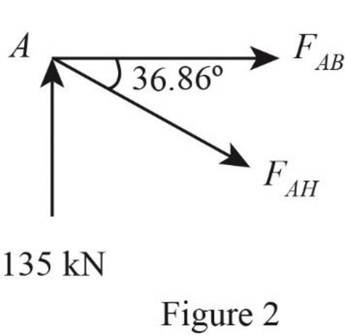
Show the joint B as shown in Figure 3.
Refer Figure 3.
Find the forces in the member BH and BC as follows:
For Equilibrium of forces,
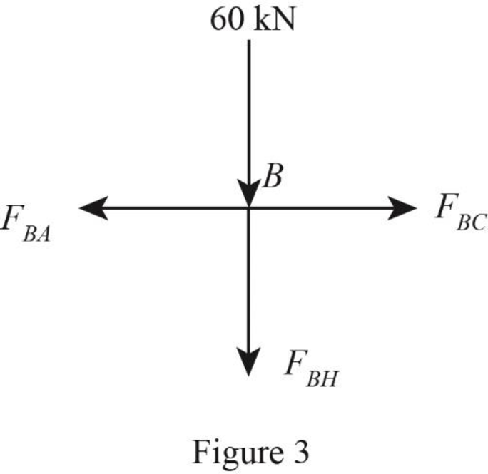
Show the joint H as shown in Figure 4.
Refer Figure 4.
Find the forces in the member HI and HC as follows:
For Equilibrium of forces,
Show the joint C as shown in Figure 5.
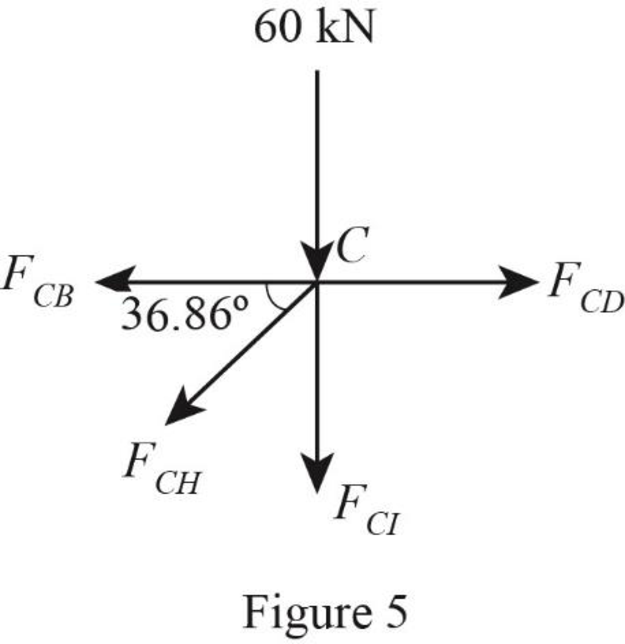
Refer Figure 5.
Find the forces in the member CD and CI as follows:
For Equilibrium of forces,
Show the joint I as shown in Figure 6.
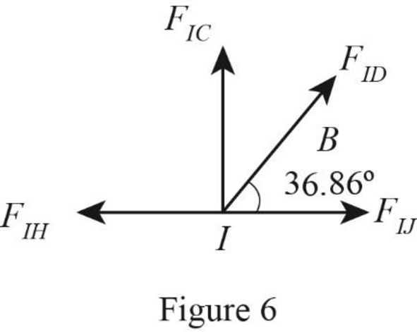
Refer Figure 6.
Find the forces in the member ID and IJ as follows:
For Equilibrium of forces,
Show the joint J as shown in Figure 7.
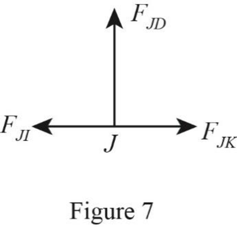
Refer Figure 7.
Find the forces in the member JD and JK as follows:
For Equilibrium of forces,
Show the joint G as shown in Figure 8.
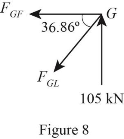
Refer Figure 8.
Find the forces in the member GL and GF as follows:
For Equilibrium of forces,
Show the joint F as shown in Figure 9.
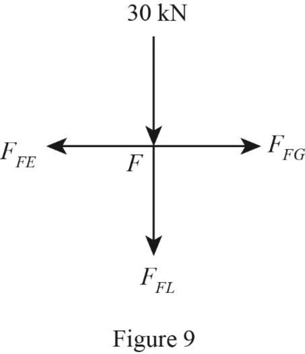
Refer Figure 9.
Find the forces in the member FE and FL as follows:
For Equilibrium of forces,
Show the joint L as shown in Figure 10.
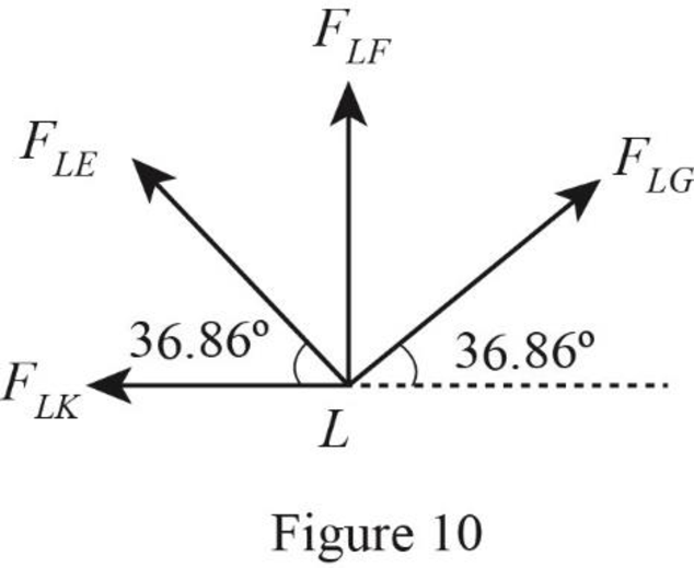
Refer Figure 10.
Find the forces in the member LE and LK as follows:
For Equilibrium of forces,
Show the joint E as shown in Figure 11.

Refer Figure 11.
Find the forces in the member EK and ED as follows:
For Equilibrium of forces,
Show the joint K as shown in Figure 12.
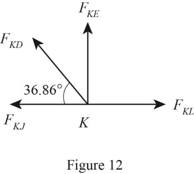
Refer Figure 12.
Find the forces in the member KD and KL as follows:
For Equilibrium of forces,
Show the forces in the members of truss as shown in Table 1.
| Member | Force (kN) |
| AB | 180 kN (C) |
| BC | 180 kN (C) |
| CD | 280 kN (C) |
| DE | 240 kN (C) |
| EF | 140 kN (C) |
| FG | 140 kN (C) |
| AH | 225 kN (T) |
| HI | 280 kN (T) |
| IJ | 300 kN (T) |
| JK | 300 kN (T) |
| KL | 240 kN (T) |
| LG | 175 kN (T) |
| BH | 60 kN (C) |
| HC | 125 kN (C) |
| CI | 15 kN (T) |
| ID | 25 kN (C) |
| DJ | 0 kN |
| DK | 75 kN (C) |
| KE | 45 kN (T) |
| EL | 125 kN (C) |
| LF | 30 kN (C) |
Want to see more full solutions like this?
Chapter 4 Solutions
Structural Analysis, SI Edition


- Please explain step by steparrow_forwardProblem 1 = = = 13,600 Manometers can be used in combination with cardiovascular catheters to measure blood pressure based on height differences. In the example in Figure 1, the manometer contains two fluids: water (density p 995 Kg/m³) and mercury (density pm Kg/m³). The density of blood is p 1,060 Kg/m³. Assume that there is atmospheric pressure at the interface between mercury and air. The interface between mercury and water is at z₁ = 7 cm, the interface between water and blood is at Z2 27 cm, and the tip of the manometer at za 10 cm. Recall that the fluid statics equation is dp/dz-pg 0, when the z axis is taken pointing downwards. a. What is the gauge pressure po at the interface with air, in mmHg? (5 points) b. Calculate the gauge pressure ps at the tip of the manometer, in mmHg. (5 points) N Z37 blood ப Zz Water Mercury Zo 3=0 z Figure 1. Manometer for blood pressure measurement.arrow_forwardDetermine the following for the beam with unknown loading, using the Shear and Bending Diagrams provided in the figures on the right: a. The maximum shear stress experienced by the beam. b. The maximum flexural stress experienced by the beam (Indicate if this is tensile or compressive flexural stress) c. The loading diagram (Indicate the magnitudes of the loading/s. The loads are acting along the plane of symmetry of the section) 20 80 20 十十 SHEAR DIAGRAM x=577.3502692 mm 20 KN 1° 5/3 KN 2° C 2° D A B CROSS SECTION Dimensions are in mm LOADING DIAGRAM ? 120 40 40 A B C D 1000mm 2000mm 1000mm -55/3 KN MB' C D BENDING DIAGRAM MB A B Σ Mcarrow_forward
- Find the maximum bending stress in ksi for this beam if it is made from a W16x50 steel shape. If the steel yields at 50 ksi, will the beam support the loads shown without permanently deforming? Confirm the max moment in the beam by drawing the shear and moment diagram. 18 kip-ft 2 kip/ft 9 ftarrow_forwardProblem 4 A propped cantilever beam of flexural rigidity EI and 2EI for parts 1-2 and 2-3, respectively, is subjected to a concentrated load P at point 2. Find: a) Determine the displacement at point 2; b) Determine the rotation at point 3; c) Determine the reaction force and moment at point 1; d) Determine the reaction force at point 3. El 2 P 2 EI 2 Larrow_forwardProblem 3 15 A W150 x 37 rolled-steel beam is used below. Let P150 kN, L-10 m and E 200 GPa. Find the deflection and slope at each node and each pin or wall reaction. If a software program such Maple or MATLAB issued as part of the solution, a hard copy of the code must be submitted too. 1/2 1/2arrow_forward
- 1. Determine the bearings, azimuths, and lengths of lines AB, BC, CD, and DA for the closed loop traverse data shown below in Table 1. Show calculations. Table 1 Station Northing [ft] Easting [ft] A 1,000 1,000 B 750 1,750 C 1,345 2,255 D 1,567 1,345 2. Compute the bearings of sides BC and CD in Figure 1. Show all work for all angles. A B 70°10' S72°39'W C 94°35' Figure 1 Tt (+) B Darrow_forwardhoph - AT 10x AT 10.076 ht 0.076 0 0-1846112 14884 xh T 1.632m h-4- (1-22) h = 1.022m 14. The 4-ft-diameter cylinder, 4 ft long, is acted upon by water on the left and oil of sp gr 0.800 on the right. Determine (a) the normal force at B if the cylinder weighs 4000 lb and (b) the horizontal force due to oil and water if the oil level drops 1 ft. Solution Water Oil Barrow_forward3. The following data was collected for the traverse shown in Figure 2. a. Determine the latitudes and departures for all sides. b. Determine the linear error of closure and the accuracy ratio. C. Correct and balance the latitudes and departures. A N80°27'E 467.81 ft 497.50 ft N56°46' W B S34°51'E 483.69 ft 325.06 ft D N81°48' Warrow_forward
- Please answer the questions in the picture. Thank you for your help!arrow_forward1500 N A B 3500 N/m 1.2 m 3.6 m 1.2 m 1800 N Beam Cross-section: 4b T D b 25 mm 100 mm For beam ABCD with cross-section shown, design the beam by determining the following: Draw the shear and bending moment diagrams (show your detailed computations to get credit) The minimum dimension for b [mm], knowing that the allowable flexural stress and transverse shear stress are 10 MPa and 0.5 MPa, respectively.arrow_forwardCivil engineering quantiarrow_forward
