Concept explainers
Videos
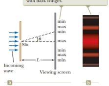
Suppose the slit width in Figure 37.4 is made half as wide. Does the central bright fringe (a) become wider, (b) remain the same, or (c) become narrower?
Figure 37.4 (a) Geometry for analyzing the Fraunhofer diffraction pattern of a single slit. (Drawing not to scale.) (b) Simulation of a single-slit Fraunhofer diffraction pattern.
Answer to Problem 38.1QQ
Explanation of Solution
Consider the figure given below.
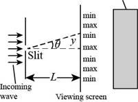
Figure (1)
The condition for the central diffraction maximum is,
Here;
From the figure (1),
Here
From the trigonometry property, for very small angle,
Substitute
Substitute
For the case of central bright fringe, the order of the fringe is
Substitute
For
Rearrange the above equation for
Thus from above equation the central bright fringe width is inversely proportional to the slit width. Thus, if the slit width decreases or half of the initial value the width of central bight fringe increases.
Conclusion:
The width of the central bright fringe is inversely proportional to the slit width so, if the slit width decreases the width of central bright fringe increases. Thus option (a) is correct.
The slit width is half of the initial value and there is inverse dependence of width of central maxima and slit width so decrease in slit width widens the central bright fringe. Thus option (b) is incorrect.
The width of the central bright fringe is inversely proportional; so decrease in slit width will increase width. Thus option (c) is incorrect.
Want to see more full solutions like this?
Chapter 38 Solutions
Bundle: Physics for Scientists and Engineers, Technology Update, 9th Loose-leaf Version + WebAssign Printed Access Card, Multi-Term


- No chatgpt pls will upvote instantarrow_forwardKirchoff's Laws. A circuit contains 3 known resistors, 2 known batteries, and 3 unknown currents as shown. Assume the current flows through the circuit as shown (this is our initial guess, the actual currents may be reverse). Use the sign convention that a potential drop is negative and a potential gain is positive. E₂ = 8V R₁₁ = 50 R₂ = 80 b с w 11 www 12 13 E₁ = 6V R3 = 20 a) Apply Kirchoff's Loop Rule around loop abefa in the clockwise direction starting at point a. (2 pt). b) Apply Kirchoff's Loop Rule around loop bcdeb in the clockwise direction starting at point b. (2 pt). c) Apply Kirchoff's Junction Rule at junction b (1 pt). d) Solve the above 3 equations for the unknown currents I1, 12, and 13 and specify the direction of the current around each loop. (5 pts) I1 = A 12 = A 13 = A Direction of current around loop abef Direction of current around loop bcde (CW or CCW) (CW or CCW)arrow_forwardNo chatgpt pls will upvotearrow_forward
- 4.) The diagram shows the electric field lines of a positively charged conducting sphere of radius R and charge Q. A B Points A and B are located on the same field line. A proton is placed at A and released from rest. The magnitude of the work done by the electric field in moving the proton from A to B is 1.7×10⁻¹⁶ J. Point A is at a distance of 5.0×10⁻²m from the centre of the sphere. Point B is at a distance of 1.0×10⁻¹ m from the centre of the sphere. (a) Explain why the electric potential decreases from A to B. [2] (b) Draw, on the axes, the variation of electric potential V with distance r from the centre of the sphere. R [2] (c(i)) Calculate the electric potential difference between points A and B. [1] (c(ii)) Determine the charge Q of the sphere. [2] (d) The concept of potential is also used in the context of gravitational fields. Suggest why scientists developed a common terminology to describe different types of fields. [1]arrow_forward3.) The graph shows how current I varies with potential difference V across a component X. 904 80- 70- 60- 50- I/MA 40- 30- 20- 10- 0+ 0 0.5 1.0 1.5 2.0 2.5 3.0 3.5 4.0 4.5 5.0 VIV Component X and a cell of negligible internal resistance are placed in a circuit. A variable resistor R is connected in series with component X. The ammeter reads 20mA. 4.0V 4.0V Component X and the cell are now placed in a potential divider circuit. (a) Outline why component X is considered non-ohmic. [1] (b(i)) Determine the resistance of the variable resistor. [3] (b(ii)) Calculate the power dissipated in the circuit. [1] (c(i)) State the range of current that the ammeter can measure as the slider S of the potential divider is moved from Q to P. [1] (c(ii)) Describe, by reference to your answer for (c)(i), the advantage of the potential divider arrangement over the arrangement in (b).arrow_forward1.) Two long parallel current-carrying wires P and Q are separated by 0.10 m. The current in wire P is 5.0 A. The magnetic force on a length of 0.50 m of wire P due to the current in wire Q is 2.0 × 10-s N. (a) State and explain the magnitude of the force on a length of 0.50 m of wire Q due to the current in P. [2] (b) Calculate the current in wire Q. [2] (c) Another current-carrying wire R is placed parallel to wires P and Q and halfway between them as shown. wire P wire R wire Q 0.05 m 0.05 m The net magnetic force on wire Q is now zero. (c.i) State the direction of the current in R, relative to the current in P.[1] (c.ii) Deduce the current in R. [2]arrow_forward
- 2.) A 50.0 resistor is connected to a cell of emf 3.00 V. The voltmeter and the ammeter in the circuit are ideal. V A 50.00 (a) The current in the ammeter is 59.0 mA. Calculate the internal resistance of the cell. The circuit is changed by connecting another resistor R in parallel to the 50.0 resistor. V A 50.00 R (b) Explain the effect of this change on R is made of a resistive wire of uniform cross-sectional area 3.1 × 10⁻⁸ m², resistivity 4.9 × 10-70m and length L. The resistance of R is given by the equation R = KL where k is a constant. (b.i) the reading of the ammeter. [2] (b.ii) the reading of the voltmeter. [2] (c) Calculate k. State an appropriate unit for your answer. [3] [2]arrow_forwardNo chatgpt pls will upvotearrow_forwardNo chatgpt pls will upvotearrow_forward
 Physics for Scientists and Engineers: Foundations...PhysicsISBN:9781133939146Author:Katz, Debora M.Publisher:Cengage Learning
 Principles of Physics: A Calculus-Based TextPhysicsISBN:9781133104261Author:Raymond A. Serway, John W. JewettPublisher:Cengage Learning
 University Physics Volume 3PhysicsISBN:9781938168185Author:William Moebs, Jeff SannyPublisher:OpenStax
 Physics for Scientists and Engineers with Modern ...PhysicsISBN:9781337553292Author:Raymond A. Serway, John W. JewettPublisher:Cengage Learning
 Glencoe Physics: Principles and Problems, Student...PhysicsISBN:9780078807213Author:Paul W. ZitzewitzPublisher:Glencoe/McGraw-Hill
 Physics for Scientists and EngineersPhysicsISBN:9781337553278Author:Raymond A. Serway, John W. JewettPublisher:Cengage Learning