
Engineering Mechanics: Statics
13th Edition
ISBN: 9780132915540
Author: Russell C. Hibbeler
Publisher: Prentice Hall
expand_more
expand_more
format_list_bulleted
Concept explainers
Videos
Textbook Question
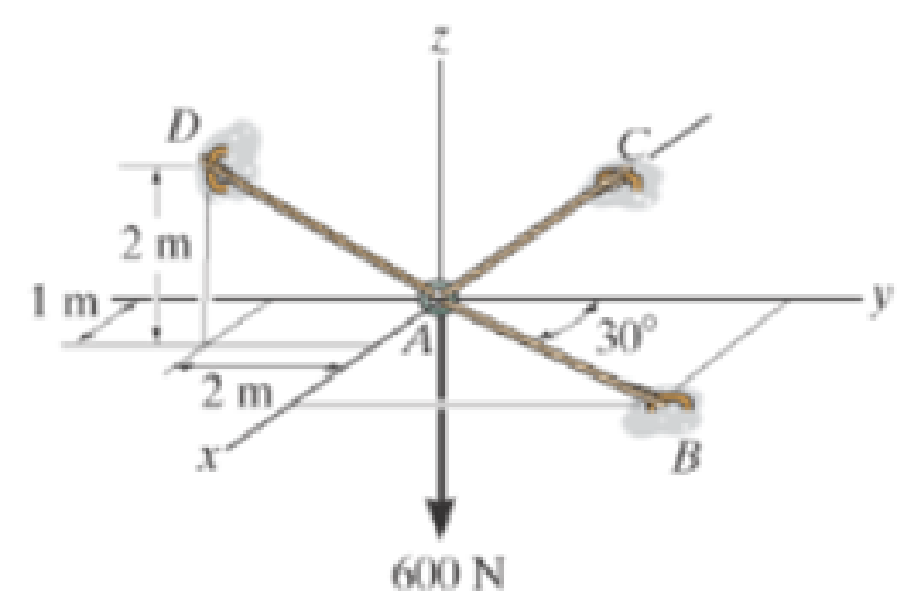
Chapter 3.4, Problem 9FP
Determine the tension developed in cables AB, AC, and AD.
Expert Solution & Answer

Learn your wayIncludes step-by-step video

schedule07:03
Students have asked these similar questions
The gears shown in the figure have a diametral pitch of 2 teeth per inch and a 20° pressure angle.
The pinion rotates at 1800 rev/min clockwise and transmits 200 hp through the idler pair to gear
5 on shaft c. What forces do gears 3 and 4 transmit to the idler shaft?
TS
I
y
18T
32T
This
a
12
x
18T
C
48T
5
Question 1. Draw 3 teeth for the following pinion and gear respectively. The teeth
should be drawn near the pressure line so that the teeth from the pinion should
mesh those of the gear. Drawing scale (1:1). Either a precise hand drawing or
CAD drawing is acceptable. Draw all the trajectories of the involute lines and the
circles.
Specification: 18tooth pinion and 30tooth gear. Diameter pitch=P=6 teeth /inch.
Pressure angle:20°, 1/P for addendum (a) and 1.25/P for dedendum (b). For fillet,
c=b-a.
5. The figure shows a gear train. There is no friction at the bearings except for the gear tooth forces.
The material of the milled gears is steel having a Brinell hardness of 170. The input shaft speed (n2)
is 800 rpm. The face width and the contact angle for all gears are 1 in and 20° respectively. In this
gear set, the endurance limit (Se) is 15 kpsi and nd (design factor) is 2.
(a) Find the revolution speed of gear 5.
(b) Determine whether each gear satisfies the design factor of 2.0 for bending fatigue.
(c) Determine whether each gear satisfies the design factor of 2.0 for surface fatigue (contact stress).
(d) According to the computation results of the questions (b) and (c), explain the possible failure
mechanisms for each gear.
N4=28
800rpm
N₁=43
N5=34
N₂=14
P(diameteral pitch)=8 for all gears
Coupled to 2.5hp motor
Chapter 3 Solutions
Engineering Mechanics: Statics
Ch. 3.3 - Determine the force in each supporting cable.Ch. 3.3 - Determine the shortest cable ABC that can be used...Ch. 3.3 - Neglect the size of the pulley.Ch. 3.3 - Determine the unstretched length of the spring.Ch. 3.3 - If the mass of cylinder C is 40 kg, determine the...Ch. 3.3 - Also, find the angle .Ch. 3.3 - Determine the magnitudes of F1 and F2 for...Ch. 3.3 - Determine the magnitude of F1 and its angle for...Ch. 3.3 - Determine the force in each of the cables AB and...Ch. 3.3 - Prob. 4P
Ch. 3.3 - Prob. 5PCh. 3.3 - Prob. 6PCh. 3.3 - Prob. 7PCh. 3.3 - Prob. 8PCh. 3.3 - Determine the maximum weight of the flowerpot that...Ch. 3.3 - Prob. 10PCh. 3.3 - Prob. 11PCh. 3.3 - Prob. 12PCh. 3.3 - Prob. 13PCh. 3.3 - Prob. 14PCh. 3.3 - Prob. 15PCh. 3.3 - Prob. 16PCh. 3.3 - Note that s = 0 when the cylinders are removed.Ch. 3.3 - The springs are shown in the equilibrium position.Ch. 3.3 - If the block is held in the equilibrium position...Ch. 3.3 - Determine the horizontal force F applied to the...Ch. 3.3 - Determine the displacement d of the cord from the...Ch. 3.3 - If the spring has an unstretched length of 2 ft,...Ch. 3.3 - Cord AB is 2 ft long. Take k = 50 lb/ft.Ch. 3.3 - Prob. 24PCh. 3.3 - Prob. 25PCh. 3.3 - Prob. 26PCh. 3.3 - Prob. 27PCh. 3.3 - Determine the tension developed in each cord...Ch. 3.3 - Determine the maximum mass of the lamp that the...Ch. 3.3 - Prob. 30PCh. 3.3 - Prob. 31PCh. 3.3 - Prob. 32PCh. 3.3 - Prob. 33PCh. 3.3 - Prob. 34PCh. 3.3 - Determine the position x and the tension developed...Ch. 3.3 - Determine the position x and the tension in the...Ch. 3.3 - If the cable can be attached at either points A...Ch. 3.3 - Prob. 38PCh. 3.3 - The cord is fixed to a pin at A and passes over...Ch. 3.3 - Prob. 40PCh. 3.3 - Take F = 300 N and d = 1 m.Ch. 3.3 - If a force of F = 100 N is applied horizontally to...Ch. 3.3 - Establish appropriate dimensions and use an...Ch. 3.3 - If the maximum tension that can be supported by...Ch. 3.3 - If the angle between AB and BC is 30, determine...Ch. 3.3 - If the distance BC is 1.5 m, and AB can support a...Ch. 3.4 - Determine the magnitude of forces F1, F2, F3, so...Ch. 3.4 - Determine the tension developed in cables AB, AC,...Ch. 3.4 - Determine the tension developed in cables AB, AC,...Ch. 3.4 - F310. Determine the tension developed in cables...Ch. 3.4 - Determine the tension in these wires.Ch. 3.4 - Prob. 43PCh. 3.4 - If cable AB is subjected to a tension of 700 N,...Ch. 3.4 - Determine the magnitudes of F1, F2, and F3 for...Ch. 3.4 - If the bucket and its contents have a total weight...Ch. 3.4 - Each spring has on unstretched length of 2 m and a...Ch. 3.4 - Prob. 48PCh. 3.4 - Prob. 49PCh. 3.4 - Prob. 50PCh. 3.4 - Prob. 51PCh. 3.4 - Prob. 52PCh. 3.4 - Prob. 53PCh. 3.4 - Determine the tens on developed in cables AB and...Ch. 3.4 - Also, what is the force developed along strut AD?Ch. 3.4 - Prob. 56PCh. 3.4 - Prob. 57PCh. 3.4 - Determine the tension developed in each cable for...Ch. 3.4 - Determine the maximum weight of the crate that can...Ch. 3.4 - Determine the force in each chain for equilibrium....Ch. 3.4 - If cable AD is tightened by a turnbuckle and...Ch. 3.4 - If cable AD is tightened by a turnbuckle and...Ch. 3.4 - Prob. 63PCh. 3.4 - Prob. 64PCh. 3.4 - Prob. 65PCh. 3.4 - Prob. 66PCh. 3.4 - Prob. 67PCh. 3.4 - If the bolt exerts a force of 50 lb on the pipe in...Ch. 3.4 - Determine the magnitude of the applied vertical...Ch. 3.4 - Prob. 70RPCh. 3.4 - Prob. 71RPCh. 3.4 - Prob. 72RPCh. 3.4 - Prob. 73RPCh. 3.4 - Also, what is the force in cord AB? Hint: use the...Ch. 3.4 - Prob. 75RPCh. 3.4 - Determine the force in each cable needed to...Ch. 3.4 - Prob. 77RP
Additional Engineering Textbook Solutions
Find more solutions based on key concepts
Distinguish among data definition commands, data manipulation commands, and data control commands.
Modern Database Management
Write a recursive method that will compute the sum of all the values in an array.
Java: An Introduction to Problem Solving and Programming (8th Edition)
Suppose the memory cells at addresses 0x00 through 0x05 in the Vole contain the following bit patterns: Address...
Computer Science: An Overview (13th Edition) (What's New in Computer Science)
TeamLeader Class In a particular factory, a team leader is an hourly paid production worker that leads a small ...
Starting Out with Java: From Control Structures through Objects (7th Edition) (What's New in Computer Science)
The same formatting techniques used with _______________ may also be used when writing data to a file.
Starting Out with C++ from Control Structures to Objects (9th Edition)
List the five major hardware components of a computer system.
Starting Out With Visual Basic (8th Edition)
Knowledge Booster


Learn more about
Need a deep-dive on the concept behind this application? Look no further. Learn more about this topic, mechanical-engineering and related others by exploring similar questions and additional content below.Similar questions
- 1. The rotating steel shaft is simply supported by bearings at points of B and C, and is driven by a spur gear at D, which has a 6-in pitch diameter. The force F from the drive gear acts at a pressure angle of 20°. The shaft transmits a torque to point A of TA =3000 lbĘ in. The shaft is machined from steel with Sy=60kpsi and Sut=80 kpsi. (1) Draw a shear force diagram and a bending moment diagram by F. According to your analysis, where is the point of interest to evaluate the safety factor among A, B, C, and D? Describe the reason. (Hint: To find F, the torque Tд is generated by the tangential force of F (i.e. Ftangential-Fcos20°) When n=2.5, K=1.8, and K₁ =1.3, determine the diameter of the shaft based on (2) static analysis using DE theory (note that fatigue stress concentration factors need to be used for this question because the loading condition is fatigue) and (3) a fatigue analysis using modified Goodman. Note) A standard diameter is not required for the questions. 10 in Darrow_forward3 N2=28 P(diametral pitch)=8 for all gears Coupled to 25 hp motor N3=34 Full depth spur gears with pressure angle=20° N₂=2000 rpm (1) Compute the circular pitch, the center-to-center distance, and base circle radii. (2) Draw the free body diagram of gear 3 and show all the forces and the torque. (3) In mounting gears, the center-to-center distance was reduced by 0.1 inch. Calculate the new values of center-to-center distance, pressure angle, base circle radii, and pitch circle diameters. (4)What is the new tangential and radial forces for gear 3? (5) Under the new center to center distance, is the contact ratio (mc) increasing or decreasing?arrow_forward2. A flat belt drive consists of two 4-ft diameter cast-iron pulleys spaced 16 ft apart. A power of 60 hp is transmitted by a pulley whose speed is 380 rev/min. Use a service factor (Ks) pf 1.1 and a design factor 1.0. The width of the polyamide A-3 belt is 6 in. Use CD=1. Answer the following questions. (1) What is the total length of the belt according to the given geometry? (2) Find the centrifugal force (Fc) applied to the belt. (3) What is the transmitted torque through the pulley system given 60hp? (4) Using the allowable tension, find the force (F₁) on the tight side. What is the tension at the loose side (F2) and the initial tension (F.)? (5) Using the forces, estimate the developed friction coefficient (f) (6) Based on the forces and the given rotational speed, rate the pulley set. In other words, what is the horse power that can be transmitted by the pulley system? (7) To reduce the applied tension on the tight side, the friction coefficient is increased to 0.75. Find out the…arrow_forward
- The tooth numbers for the gear train illustrated are N₂ = 24, N3 = 18, №4 = 30, №6 = 36, and N₁ = 54. Gear 7 is fixed. If shaft b is turned through 5 revolutions, how many turns will shaft a make? a 5 [6] barrow_forwardCE-112 please solve this problem step by step and give me the correct answerarrow_forwardCE-112 please solve this problem step by step and give me the correct answerarrow_forward
- CE-112 solve this problem step by step and give me the correct answer pleasearrow_forwardPlease do not use any AI tools to solve this question. I need a fully manual, step-by-step solution with clear explanations, as if it were done by a human tutor. No AI-generated responses, please.arrow_forwardPlease do not use any AI tools to solve this question. I need a fully manual, step-by-step solution with clear explanations, as if it were done by a human tutor. No AI-generated responses, please.arrow_forward
arrow_back_ios
SEE MORE QUESTIONS
arrow_forward_ios
Recommended textbooks for you
 International Edition---engineering Mechanics: St...Mechanical EngineeringISBN:9781305501607Author:Andrew Pytel And Jaan KiusalaasPublisher:CENGAGE L
International Edition---engineering Mechanics: St...
Mechanical Engineering
ISBN:9781305501607
Author:Andrew Pytel And Jaan Kiusalaas
Publisher:CENGAGE L
Engineering Basics - Statics & Forces in Equilibrium; Author: Solid Solutions - Professional Design Solutions;https://www.youtube.com/watch?v=dQBvQ2hJZFg;License: Standard YouTube License, CC-BY