
MECHANICS OF MATERIALS
11th Edition
ISBN: 9780137605385
Author: HIBBELER
Publisher: PEARSON
expand_more
expand_more
format_list_bulleted
Videos
Textbook Question
Chapter 3.4, Problem 4P
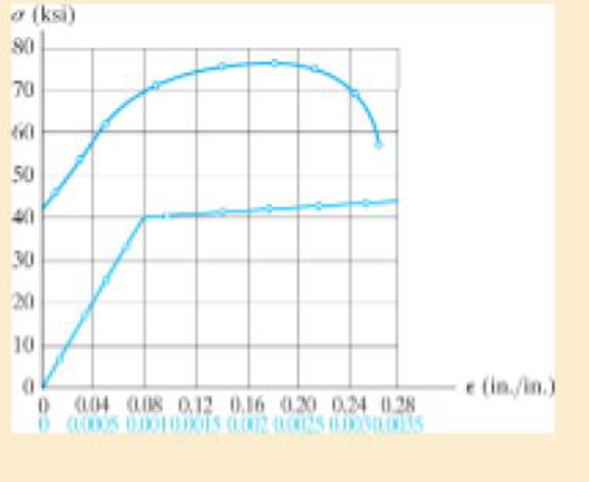
The stress-strain diagram for a steel alloy having an original diameter of 0.5 in. and a gage length of 2 in. is given in the figure. Determine approximately the modulus of elasticity for the material, the load on the specimen that causes yielding, and the ultimate load the specimen will support.
Prob. 3–4
Expert Solution & Answer
Want to see the full answer?
Check out a sample textbook solution
Students have asked these similar questions
mylabmastering.pearson.com
Chapter 12 - Lecture Notes.pptx: (MAE 272-01) (SP25) DY...
P Pearson MyLab and Mastering
Scores
A metal plate of thickness 200 mm with thermal diffusivity 5.6 x10⁻⁶ m²/s and thermal
conductivity 20 W/mK is initially at a uniform temperature of 325°C. Suddenly, the 2 sides of
the plate are exposed to a coolant at 15°C for which the convection heat transfer coefficient is
100 W/m²K. Determine temperatures at the surface of the plate after 3 min using
(a) Lumped system analysis
(b) Analytical one term approximation
(c) One dimensional Semi infinite solid
Analyze and discuss the results
Problem 3
This problem maps back to learning
objectives 1-4 & 8.
Consider the particle attached to a spring shown below. The particle
has a mass m and the spring has a spring constant k. The mass-spring
system makes an angle of 0 with respect to the vertical and the
distance between point 0 and the particle can be defined as r. The
spring is unstretched when r = l.
Ꮎ
g
m
a) How many degrees of freedom is this system and what are
they?
b) Derive the equation(s) of motion that govern the movement of
this system.
Chapter 3 Solutions
MECHANICS OF MATERIALS
Ch. 3.4 - Define a homogeneous material.Ch. 3.4 - Indicate the points on the stress-strain diagram...Ch. 3.4 - Define the modulus of elasticity E.Ch. 3.4 - At room temperature, mild steel is a ductile...Ch. 3.4 - Engineering stress and strain are calculated using...Ch. 3.4 - As the temperature increases the modulus of...Ch. 3.4 - A 100-mm-long rod has a diameter of 15 mm. If an...Ch. 3.4 - A bar has a length of 8 in. and cross-sectional...Ch. 3.4 - A 10-mm-diameter rod has a modulus of elasticity...Ch. 3.4 - The material for the 50-mm-long specimen has the...
Ch. 3.4 - The material for the 50-mm-long specimen has the...Ch. 3.4 - If the elongation of wire BC is 0.2 mm after the...Ch. 3.4 - Data taken from a stress-strain test for a ceramic...Ch. 3.4 - The stress-strain diagram for a steel alloy having...Ch. 3.4 - The stress-strain diagram for a steel alloy having...Ch. 3.4 - The stress-strain diagram for a steel alloy having...Ch. 3.4 - Determine the elongation of the square hollow bar...Ch. 3.4 - The stress-strain diagram for an aluminum alloy...Ch. 3.4 - The stress-strain diagram for an aluminum alloy...Ch. 3.4 - The stress-strain diagram for an aluminum alloy...Ch. 3.4 - A structural member in a nuclear reactor is made...Ch. 3.4 - The rigid pipe is supported by a pin at A and an...Ch. 3.4 - The rigid pipe is supported by a pin at A and an...Ch. 3.4 - Direct tension indicators are sometimes used...Ch. 3.4 - A tension test was performed on a magnesium alloy...Ch. 3.4 - The stress-strain diagram for a bone is shown and...Ch. 3.4 - The two bars are made of a material that has the...Ch. 3.4 - The two bars are made of a material that has the...Ch. 3.7 - A 100-mm-long rod has a diameter of 15 mm. If an...Ch. 3.7 - A solid circular rod that is 600 mm long and 20 mm...Ch. 3.7 - A 20-mm-wide block is firmly bonded to rigid...Ch. 3.7 - A 20-mm-wide block is bonded to rigid plates at...Ch. 3.7 - The acrylic plastic rod is 400mm long and 20mm in...Ch. 3.7 - The elastic portion of the stress-strain diagram...Ch. 3.7 - The elastic portion of the stress-strain diagram...Ch. 3.7 - The lap joint is connected together using a 1.25...Ch. 3.7 - The lap joint is connected together using a 1.25...Ch. 3.7 - Prob. 32PCh. 3.7 - The thin-walled tube is subjected to an axial...Ch. 3 - The elastic portion of the tension stress-strain...Ch. 3 - The elastic portion of the tension stress-strain...Ch. 3 - The rigid beam rests in the horizontal position on...Ch. 3 - The wires each have a diameter of 12 in., length...Ch. 3 - Prob. 5RPCh. 3 - diameter steel bolts. If the clamping force in...Ch. 3 - The stress-strain diagram for polyethylene, which...Ch. 3 - The pipe with two rigid caps attached to its ends...Ch. 3 - The 8-mm-diameter bolt is made of an aluminum...Ch. 3 - An acetal polymer block is fixed to the rigid...
Knowledge Booster


Learn more about
Need a deep-dive on the concept behind this application? Look no further. Learn more about this topic, mechanical-engineering and related others by exploring similar questions and additional content below.Similar questions
- Chapter 12 - Lecture Notes.pptx: (MAE 272-01) (SP25) DY... Scores ■Review Determine the maximum constant speed at which the pilot can travel, so that he experiences a maximum acceleration an = 8g = 78.5 m/s². Express your answer to three significant figures and include the appropriate units. μΑ v = Value Units Submit Request Answer Part B ? Determine the normal force he exerts on the seat of the airplane when the plane is traveling at this speed and is at its lowest point. Express your answer to three significant figures and include the appropriate units. о HÅ N = Value Submit Request Answer Provide Feedback ? Units Next >arrow_forwardI want to know the Milankovich orbital element constraint equation. Is it e*cos(i) = cos(argp), where e is eccentricity, i is inclination, and argp is arguement of periapsisarrow_forwardThe following data were taken during a one-hour trial run on a single cylinder, single acting, four-stroke diesel engine of cylinder diameter of 175 mm and stroke 225 mm , the speed being constant at 1000 rpm : Indicated mep: 5.5 barsDiam. of rope brake: 1066 mmLoad on brake: 400 NReading of balance: 27 NFuel consumed: 5.7 kgCalorific value: 44.2 MJ/kg Calculate the indicated power, brake power, specific fuel consumption per indicated kWh and per brake kWh , mechanical efficiency, indicated thermal and brake thermal efficiency.arrow_forward
- mylabmastering.pearson.com Chapter 12 - Lecture Notes.pptx: (MAE 272-01) (SP25) DY... Document Sharing P Pearson MyLab and Mastering User Settings Part A P Course Home b Success Confirmation of Question Submission | bartleby A particle moves along an Archimedean spiral r = (80) ft, where 0 is given in radians. (Figure 1) If ė = = 4 rad/s and € = 5 rad/s², determine the radial component of the particle's velocity at the instant Express your answer to three significant figures and include the appropriate units. Figure y r = Α ? Vr = Value Units Submit Request Answer Part B Determine the transverse component of the particle's velocity. Express your answer to three significant figures and include the appropriate units. о MÅ ve = Value Submit Request Answer Part C Units ? 1 of 1 Determine the radial component of the particle's acceleration. Express your answer to three significant figures and include the appropriate units. Ar = (80) ft о ΜΑ Value Units ? = π/2 rad.arrow_forwardCan you help me with a matlab code? I am trying to plot the keplerian orbital elements over time. I would usually find the orbit using cartesian system and then transform into keplerian orbital elements. Is there a way to directly integrate keplerian orbital elements?arrow_forwardmylabmastering.pearson.com Chapter 12 - Lecture Notes.pptx: (MAE 272-01) (SP25) DY... P Pearson MyLab and Mastering Scoresarrow_forward
- K mylabmastering.pearson.com Chapter 12 - Lecture Notes.pptx: (MAE 272-01) (SP25) DY... P Pearson MyLab and Mastering Mastering Engineering Back to my courses Course Home Scores Course Homearrow_forwardK mylabmastering.pearson.com Chapter 12 - Lecture Notes.pptx: (MAE 272-01) (SP25) DY... P Pearson MyLab and Mastering Mastering Engineering Back to my courses Course Home Scores Course Homearrow_forwardChapter 12 - Lecture Notes.pptx: (MAE 272-01) (SP25) DY... Scoresarrow_forwardIn a single cylinder, four stroke, single acting gas engine, the cylinder diameter is 180 mm and the stroke is 350 mm . When running at 250 rpm , the mean area of the indicator diagram taken off the engine is 355 mm² , length of diagram 75 mm , scale of the indicator spring 90 kN/m sq per mm , and the number of explosions was counted to be 114 per minute. Calculate the indicated power. so i have already asked this question and got a good answer, however on step 4, i dont understand how they reached 18.43 KW. When i do the math provided, i get the answer 7195.566. Where am i going wrong? thanks StepsTo clarify how we determined the Indicated Power, I'll go over each step in detail. Step 1: Comprehending the Provided Information - Cylinder diameter (in meters) = 180 mm = 0.18 m - Stroke length (in meters) = 350 mm = 0.35 m - Engine speed = 250 rpm -Indicator diagram mean area = 355 mm² The diagram's length is 75 mm; its spring scale is 90 kN/m² per mm, or 90,000 N/m² per mm; and…arrow_forwardIn MATLAB, can you help me simulate an orbit under earth J2 perturbation with the Milankovich orbital elements? Also, can you check to see if they fit the Milankovich constraint equaiton?arrow_forward8. All of the members in the Warren truss of Figure 8 are of length 10 ft. Use the method of sections to determine the forces in the members BD,CD,CE. B A C D E F G 2000 lb 3000 lb 5000 lb Figure 8 Harrow_forwardarrow_back_iosSEE MORE QUESTIONSarrow_forward_ios
Recommended textbooks for you
 Mechanics of Materials (MindTap Course List)Mechanical EngineeringISBN:9781337093347Author:Barry J. Goodno, James M. GerePublisher:Cengage Learning
Mechanics of Materials (MindTap Course List)
Mechanical Engineering
ISBN:9781337093347
Author:Barry J. Goodno, James M. Gere
Publisher:Cengage Learning
Lec21, Part 5, Strain transformation; Author: Mechanics of Materials (Libre);https://www.youtube.com/watch?v=sgJvz5j_ubM;License: Standard Youtube License