
Vector Mechanics for Engineers: Statics
12th Edition
ISBN: 9781259977268
Author: Ferdinand P. Beer, E. Russell Johnston Jr., David Mazurek
Publisher: McGraw-Hill Education
expand_more
expand_more
format_list_bulleted
Concept explainers
Videos
Textbook Question
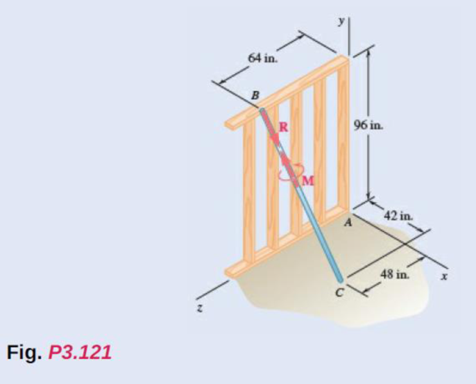
Chapter 3.4, Problem 3.121P
As an adjustable brace BC is used to bring a wall into plumb, the force-couple system shown is exerted on the wall. Replace this force-couple system with an equivalent force-couple system at A if R = 21.2 lb and M = 13.25 lb·ft.
Expert Solution & Answer
Want to see the full answer?
Check out a sample textbook solution
Students have asked these similar questions
Please also draw the FBDs
Design Description: Fresh water tank, immersed in an oil tank.a) Water tank:a. Shape: Cylindricalb. Radius: 1 meterc. Height: 3 metersd. Bottom airlock: 0.2m x 0.2m.
b) Oil tank:a. Shape: cylindricalb. Radius: 4 metersc. Oil density: 850 kg/m³
Determine:a) The pressure experienced by an airlock at the bottom of the tank with water.b) The force and direction necessary to open the lock, suppose the lock weighs 20 Newtons, suppose the lock opens outwards.
The image is for illustrative purposes, the immersed cylinder does not reach the bottom
Need help!
Chapter 3 Solutions
Vector Mechanics for Engineers: Statics
Ch. 3.1 - A foot valve for a pneumatic system is hinged at...Ch. 3.1 - 3.2A foot valve for a pneumatic system is hinged...Ch. 3.1 - It is known that a vertical force of 200 lb is...Ch. 3.1 - A 300-N force is applied at A as shown. Determine...Ch. 3.1 - A 300-N force is applied at A as shown. Determine...Ch. 3.1 - An 8-lb force P is applied to a shift lever....Ch. 3.1 - Prob. 3.7PCh. 3.1 - An 11-lb force P is applied to a shift lever. The...Ch. 3.1 - Rod AB is held in place by the cord AC. Knowing...Ch. 3.1 - Rod AB is held in place by the cord AC. Knowing...
Ch. 3.1 - 3.11 and 3.12The tailgate of a car is supported by...Ch. 3.1 - 3.11 and 3.12The tailgate of a car is supported by...Ch. 3.1 - 3.13 and 3.14It is known that the connecting rod...Ch. 3.1 - 3.13 and 3.14It is known that the connecting rod...Ch. 3.1 - Form the vector product P1 P2 and use the result...Ch. 3.1 - The vectors P and Q are two adjacent sides of a...Ch. 3.1 - Prob. 3.17PCh. 3.1 - Prob. 3.18PCh. 3.1 - Prob. 3.19PCh. 3.1 - Prob. 3.20PCh. 3.1 - Before the trunk of a large tree is felled, cables...Ch. 3.1 - The 12-ft boom AB has a fixed end A. A steel cable...Ch. 3.1 - A 200-N force is applied as shown to the bracket...Ch. 3.1 - A force P of magnitude 200 N acts along the...Ch. 3.1 - A 6-ft-long fishing rod AB is securely anchored in...Ch. 3.1 - A precast concrete wall section is temporarily...Ch. 3.1 - In Prob. 3.22, determine the perpendicular...Ch. 3.1 - In Prob. 3.23, determine the perpendicular...Ch. 3.1 - In Prob. 3.24, determine the perpendicular...Ch. 3.1 - In Prob. 3.25, determine the perpendicular...Ch. 3.1 - In Prob. 3.25, determine the perpendicular...Ch. 3.1 - In Prob. 3.26, determine the perpendicular...Ch. 3.1 - In Prob. 3.26, determine the perpendicular...Ch. 3.1 - Determine the value of a that minimizes the...Ch. 3.2 - Given the vectors P = 2i + j + 2k, Q = 3i + 4j ...Ch. 3.2 - Form the scalar product B C and use the result...Ch. 3.2 - Three cables are attached to the top of the tower...Ch. 3.2 - Prob. 3.38PCh. 3.2 - Knowing that the tension in cable AC is 280 lb,...Ch. 3.2 - Knowing that the tension in cable AD is 180 lb,...Ch. 3.2 - Ropes AB and BC are two of the ropes used to...Ch. 3.2 - Ropes AB and BC are two of the ropes used to...Ch. 3.2 - The 20-in. tube AB can slide along a horizontal...Ch. 3.2 - Solve Prob. 3.43 for the position corresponding to...Ch. 3.2 - Determine the volume of the parallelepiped of Fig....Ch. 3.2 - Prob. 3.46PCh. 3.2 - A crane is oriented so that the end of the 25-m...Ch. 3.2 - 3.48The 25-m crane boom AO lies in the yz plane....Ch. 3.2 - To loosen a frozen valve, a force F with a...Ch. 3.2 - 3.50When a force F is applied to the handle of the...Ch. 3.2 - The 0.61 1.00-m lid ABCD of a storage bin is...Ch. 3.2 - Prob. 3.52PCh. 3.2 - A farmer uses cables and winch pullers B and E to...Ch. 3.2 - Solve Prob. 3.53 when the tension in cable AB is...Ch. 3.2 - A force P of magnitude 520 lb acts on the frame...Ch. 3.2 - 3.56A force P acts on the frame shown at point E....Ch. 3.2 - The frame ACD is hinged at A and D and is...Ch. 3.2 - In Prob. 3.57, determine the moment about the...Ch. 3.2 - The triangular plate ABC is supported by...Ch. 3.2 - 3.60The triangular plate ABC is supported by...Ch. 3.2 - Prob. 3.61PCh. 3.2 - Prob. 3.62PCh. 3.2 - Two forces F1 and F2 in space have the same...Ch. 3.2 - Prob. 3.64PCh. 3.2 - Prob. 3.65PCh. 3.2 - In Prob. 3.57, determine the perpendicular...Ch. 3.2 - In Prob. 3.58, determine the perpendicular...Ch. 3.2 - In Prob. 3.59, determine the perpendicular...Ch. 3.2 - In Prob. 3.60, determine the perpendicular...Ch. 3.3 - Two 80-N forces are applied as shown to the...Ch. 3.3 - Two parallel 60-N forces are applied as shown to...Ch. 3.3 - A multiple-drilling machine is used to drill...Ch. 3.3 - Four pegs of the same diameter are attached to a...Ch. 3.3 - A piece of plywood in which several holes are...Ch. 3.3 - The shafts of an angle drive are acted upon by the...Ch. 3.3 - Prob. 3.76PCh. 3.3 - 3.77If P = 20 lb in the figure, replace the three...Ch. 3.3 - The two couples shown are to be replaced with a...Ch. 3.3 - Solve part a of Prob. 3.78, assuming that two 15-N...Ch. 3.3 - Shafts A and B connect the gear box to the wheel...Ch. 3.3 - A 500-N force is applied to a bent plate as shown....Ch. 3.3 - A crane column supports a 16-kip load as shown....Ch. 3.3 - A dirigible is tethered by a cable attached to its...Ch. 3.3 - A 30-lb vertical force P is applied at A to the...Ch. 3.3 - A worker tries to move a rock by applying a 360-N...Ch. 3.3 - A worker tries to move a rock by applying a 360-N...Ch. 3.3 - The shearing forces exerted on the cross section...Ch. 3.3 - Knowing that = 60, replace the force and couple...Ch. 3.3 - Three control rods attached to a lever ABC exert...Ch. 3.3 - A rectangular plate is acted upon by the force and...Ch. 3.3 - While tapping a hole, a machinist applies the...Ch. 3.3 - A hexagonal plate is acted upon by the force P and...Ch. 3.3 - Replace the 250-kN force P with an equivalent...Ch. 3.3 - A 2.6-kip force is applied at point D of the...Ch. 3.3 - Replace the 150-N force with an equivalent...Ch. 3.3 - To keep a door closed, a wooden stick is wedged...Ch. 3.3 - A 46-lb force F and a 2120-lbin. couple M are...Ch. 3.3 - A 110-N force acting in a vertical plane parallel...Ch. 3.3 - The 12-ft boom AB has a fixed end A, and the...Ch. 3.3 - The jib crane shown is oriented so that its boom...Ch. 3.4 - 3.101A 4-m-long beam is subjected to a variety of...Ch. 3.4 - Prob. 3.102PCh. 3.4 - Determine the single equivalent force and the...Ch. 3.4 - Five separate force-couple systems act at the...Ch. 3.4 - The weights of two children sitting at ends A and...Ch. 3.4 - Three stage lights are mounted on a pipe as shown....Ch. 3.4 - A beam supports three loads of given magnitude and...Ch. 3.4 - A 6 12-in. plate is subjected to four loads as...Ch. 3.4 - Gear C is rigidly attached to arm AB. If the...Ch. 3.4 - To test the strength of a 625 500-mm suitcase,...Ch. 3.4 - Two cables exert forces of 90 kN each on a truss...Ch. 3.4 - Pulleys A and B are mounted on bracket CDEF. The...Ch. 3.4 - The roof of a building frame is subjected to the...Ch. 3.4 - A couple of magnitude M = 80 lbin. and the three...Ch. 3.4 - A couple M and the three forces shown are applied...Ch. 3.4 - A machine component is subjected to the forces and...Ch. 3.4 - Solve Prob. 3.116, assuming that P = 60 N.Ch. 3.4 - As follower AB rolls along the surface of member...Ch. 3.4 - A machine component is subjected to the forces...Ch. 3.4 - Two 150-mm-diameter pulleys are mounted on line...Ch. 3.4 - As an adjustable brace BC is used to bring a wall...Ch. 3.4 - In order to unscrew the tapped faucet A, a plumber...Ch. 3.4 - Assuming = 60 in Prob. 3.122, replace the two...Ch. 3.4 - Four forces are applied to the machine component...Ch. 3.4 - A blade held in a brace is used to tighten a screw...Ch. 3.4 - A mechanic uses a crowfoot wrench to loosen a bolt...Ch. 3.4 - Prob. 3.127PCh. 3.4 - Prob. 3.128PCh. 3.4 - Four signs are mounted on a frame spanning a...Ch. 3.4 - Prob. 3.130PCh. 3.4 - A concrete foundation mat of 5-m radius supports...Ch. 3.4 - Determine the magnitude and the point of...Ch. 3.4 - Prob. 3.133PCh. 3.4 - A piece of sheet metal is bent into the shape...Ch. 3.4 - Prob. 3.135PCh. 3.4 - Prob. 3.136PCh. 3.4 - Two bolts at A and B are tightened by applying the...Ch. 3.4 - Two bolts at A and B are tightened by applying the...Ch. 3.4 - Prob. 3.139PCh. 3.4 - A flagpole is guyed by three cables. If the...Ch. 3.4 - 3.141 and 3.142Determine whether the...Ch. 3.4 - 3.141 and 3.142Determine whether the...Ch. 3.4 - Replace the wrench shown with an equivalent system...Ch. 3.4 - Show that, in general, a wrench can be replaced...Ch. 3.4 - Show that a wrench can be replaced with two...Ch. 3.4 - Show that a wrench can be replaced with two...Ch. 3 - A 300-N force P is applied at point A of the bell...Ch. 3 - A winch puller AB is used to straighten a fence...Ch. 3 - A small boat hangs from two davits, one of which...Ch. 3 - Prob. 3.150RPCh. 3 - A single force P acts at C in a direction...Ch. 3 - The 23-in. vertical rod CD is welded to the...Ch. 3 - In a manufacturing operation, three holes are...Ch. 3 - A 260-lb force is applied at A to the rolled-steel...Ch. 3 - Prob. 3.155RPCh. 3 - A 77-N force F1 and a 31-Nm couple M1 are applied...Ch. 3 - Three horizontal forces are applied as shown to a...Ch. 3 - While using a pencil sharpener, a student applies...
Knowledge Booster


Learn more about
Need a deep-dive on the concept behind this application? Look no further. Learn more about this topic, mechanical-engineering and related others by exploring similar questions and additional content below.Similar questions
- need help understanding?arrow_forward%94 KB/S Find : 1. dynamic load on each bearing due to the out-of-balance couple; and 2. kinetic energy of the complete assembly. [Ans. 6.12 kg: 8.7 N-m] L 2. 3. 4. 5. 1. 2. 5. DO YOU KNOW? Why is balancing of rotating parts necessary for high speed engines? Explain clearly the terms "static balancing' and 'dynamic balancing'. State the necessary conditions to achieve them. Discuss how a single revolving mass is balanced by two masses revolving in different planes. Chapter 21: Balancing of Rotating Masses .857 Explain the method of balancing of different masses revolving in the same plane. How the different masses rotating in different planes are balanced? OBJECTIVE TYPE QUESTIONS The balancing of rotating and reciprocating parts of an engine is necessary when it runs at (a) slow speed (b) medium speed (c) high speed A disturbing mass, attached to a rotating shaft may be balanced by a single mass m, attached in the same plane of rotation as that of my such that (a) (b) F For static…arrow_forwardProvide a real-world usage example of the following: Straightness Circularity Parallelism What specific tools, jigs, and other devices are used to control the examples you provided?arrow_forward
- 856 Theory of Machines 5. A shaft carries five masses A, B, C, D and E which revolve at the same radius in planes which are equidistant from one another. The magnitude of the masses in planes A, C and D are 50 kg, 40 kg and 80 kg respectively. The angle between A and C is 90° and that between C and D is 135° Determine the magnitude of the masses in planes B and E and their positions to put the shaft in complete rotating balance. [Ans. 12 kg, 15 kg; 130° and 24° from mass A in anticlockwise direction]arrow_forward2. 3. 4. clockwise from Four masses A, B, C and D revolve at equal radii and are equally spaced along a shaft. The mass B is 7 kg and the radii of C and D make angles of 90° and 240° respectively with the radius of B. Find the magnitude of the masses A, C and D and the angular position of A so that the system may be completely balanced. [Ans. 5 kg: 6 kg; 4.67 kg; 205° from mass B in anticlockwise direction] A rotating shaft carries four masses A, B, C and D which are radially attached to it. The mass centres are 30 mm, 38 mm, 40 mm and 35 mm respectively from the axis of rotation. The masses A, C and D are 7.5 kg. 5 kg and 4 kg respectively. The axial distances between the planes of rotation of A and B is 400 mm and between B and C is 500 mm. The masses A and C are at right angles to each other. Find for a complete balance, 1. the angles between the masses B and D from mass A, 2. the axial distance between the planes of rotation of C and D. 3. the magnitude of mass B. [Ans. 162.5%,…arrow_forward1. Four masses A, B, C and D are attached to a shaft and revolve in the same plane. The masses are 12 kg. 10 kg. 18 kg and 15 kg respectively and their radii of rotations are 40 mm, 50 mm, 60 mm and 30 mm. The angular position of the masses B, C and D are 60°, 135° and 270 from the mass A. Find the magnitude and position of the balancing mass at a radius of 100 mm. [Ans. 7.56 kg: 87 clockwise from A]arrow_forward
- 3. The structure in Figure 3 is loaded by a horizontal force P = 2.4 kN at C. The roller at E is frictionless. Find the axial force N, the shear force V and the bending moment M at a section just above the pin B in the member ABC and illustrate their directions on a sketch of the segment AB. B P D A 65° 65° E all dimensions in meters Figure 3arrow_forward4. The distributed load in Figure 4 varies linearly from 3wo per unit length at A to wo per unit length at B and the beam is built in at A. Find expressions for the shear force V and the bending moment M as functions of x. 3W0 Wo A L Figure 4 2 Barrow_forward1. The beam AB in Figure 1 is subjected to a uniformly distributed load wo = 100 N/m. Find the axial force N, the shear force V and the bending moment M at the point D which is midway between A and B and illustrate their directions on a sketch of the segment DB. wo per unit length A D' B all dimensions in metersarrow_forward
- 5. Find the shear force V and the bending moment M for the beam of Figure 5 as functions of the distance x from A. Hence find the location and magnitude of the maximum bending moment. w(x) = wox L x L Figure 5 Barrow_forwardDry atmospheric air enters an adiabatic compressor at a 20°C, 1 atm and a mass flow rate of 0.3kg/s. The air is compressed to 1 MPa. The exhaust temperature of the air is 70 degrees hottercompared to the exhaust of an isentropic compression.Determine,a. The exhaust temperature of the air (°C)b. The volumetric flow rate (L/s) at the inlet and exhaust of the compressorc. The power required to accomplish the compression (kW)d. The isentropic efficiency of the compressore. An accounting of the exergy entering the compressor (complete Table P3.9) assuming that thedead state is the same as State 1 (dry atmospheric air)f. The exergetic efficiency of the compressorarrow_forwardA heat pump is operating between a low temperature reservoir of 270 K and a high temperaturereservoir of 340 K. The heat pump receives heat at 255 K from the low temperature reservoir andrejects heat at 355 K to the high temperature reservoir. The heating coefficient of performance ofthe heat pump is 3.2. The heat transfer rate from the low temperature reservoir is 30 kW. The deadstate temperature is 270 K. Determine,a. Power input to the heat pump (kW)b. Heat transfer rate to the high-temperature reservoir (kW)c. Exergy destruction rate associated with the low temperature heat transfer (kW)d. Exergy destruction rate of the heat pump (kW)e. Exergy destruction rate associated with the high temperature heat transfer (kW)f. Exergetic efficiency of the heat pump itselfarrow_forward
arrow_back_ios
SEE MORE QUESTIONS
arrow_forward_ios
Recommended textbooks for you
 International Edition---engineering Mechanics: St...Mechanical EngineeringISBN:9781305501607Author:Andrew Pytel And Jaan KiusalaasPublisher:CENGAGE L
International Edition---engineering Mechanics: St...
Mechanical Engineering
ISBN:9781305501607
Author:Andrew Pytel And Jaan Kiusalaas
Publisher:CENGAGE L
Introduction To Engg Mechanics - Newton's Laws of motion - Kinetics - Kinematics; Author: EzEd Channel;https://www.youtube.com/watch?v=ksmsp9OzAsI;License: Standard YouTube License, CC-BY