
Physics for Scientists and Engineers: Foundations and Connections
1st Edition
ISBN: 9781133939146
Author: Katz, Debora M.
Publisher: Cengage Learning
expand_more
expand_more
format_list_bulleted
Videos
Textbook Question
Chapter 33, Problem 78PQ
Two coaxial cables of length ℓ with radii a and b are carrying currents in opposite directions as shown in Figure P33.78. Determine the inductance of the system. Hint: Use Ampére’s law to write an expression for the magnetic field in the region between the cables, a distance r from the axis of the cables. Then calculate the magnetic flux through a narrow rectangular region between the cables such that the Field is perpendicular to the area everywhere.
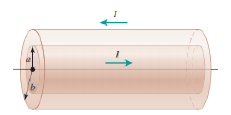
FIGURE P33.78
Expert Solution & Answer

Trending nowThis is a popular solution!

Students have asked these similar questions
19:39 ·
C
Chegg
1 69%
✓
The compound beam is fixed at Ę and supported by rollers at A and B. There are pins at C and D. Take
F=1700 lb. (Figure 1)
Figure
800 lb
||-5-
F
600 lb
بتا
D
E
C
BO
10 ft 5 ft 4 ft-—— 6 ft — 5 ft-
Solved Part A The compound
beam is fixed at E and...
Hình ảnh có thể có bản quyền. Tìm hiểu thêm
Problem
A-12
% Chia sẻ
kip
800 lb
Truy cập )
D Lưu
of
C
600 lb
|-sa+ 10ft 5ft 4ft6ft
D
E
5 ft-
Trying
Cheaa
Những kết quả này có
hữu ích không?
There are pins at C and D To F-1200 Egue!)
Chegg
Solved The compound b...
Có Không ☑
|||
Chegg
10
וח
No chatgpt pls will upvote
No chatgpt pls will upvote
Chapter 33 Solutions
Physics for Scientists and Engineers: Foundations and Connections
Ch. 33.1 - Prob. 33.1CECh. 33.1 - Prob. 33.2CECh. 33.2 - Prob. 33.3CECh. 33.3 - Prob. 33.4CECh. 33.4 - Prob. 33.5CECh. 33.5 - Prob. 33.6CECh. 33.7 - Prob. 33.7CECh. 33 - Prob. 1PQCh. 33 - Prob. 2PQCh. 33 - Prob. 3PQ
Ch. 33 - Prob. 4PQCh. 33 - Prob. 5PQCh. 33 - Prob. 6PQCh. 33 - Prob. 7PQCh. 33 - Prob. 8PQCh. 33 - Prob. 9PQCh. 33 - Prob. 10PQCh. 33 - Prob. 11PQCh. 33 - At one instant, a current of 6.0 A flows through...Ch. 33 - Prob. 13PQCh. 33 - Prob. 14PQCh. 33 - Prob. 15PQCh. 33 - In Figure 33.9A (page 1052), the switch is closed...Ch. 33 - Prob. 17PQCh. 33 - Prob. 18PQCh. 33 - Prob. 19PQCh. 33 - Prob. 20PQCh. 33 - Prob. 21PQCh. 33 - Prob. 22PQCh. 33 - In the LC circuit in Figure 33.11, the inductance...Ch. 33 - A 2.0-F capacitor is charged to a potential...Ch. 33 - Prob. 26PQCh. 33 - Prob. 27PQCh. 33 - Prob. 28PQCh. 33 - For an LC circuit, show that the total energy...Ch. 33 - Prob. 30PQCh. 33 - Prob. 31PQCh. 33 - Prob. 32PQCh. 33 - Prob. 33PQCh. 33 - Suppose you connect a small lightbulb across a DC...Ch. 33 - Prob. 35PQCh. 33 - Prob. 36PQCh. 33 - Prob. 37PQCh. 33 - Prob. 38PQCh. 33 - Prob. 39PQCh. 33 - Prob. 40PQCh. 33 - Prob. 41PQCh. 33 - Prob. 42PQCh. 33 - Prob. 43PQCh. 33 - In an ideal AC circuit with capacitance, there is...Ch. 33 - Prob. 45PQCh. 33 - Prob. 46PQCh. 33 - Prob. 47PQCh. 33 - Prob. 48PQCh. 33 - Prob. 49PQCh. 33 - An AC generator with an rms emf of 15.0 V is...Ch. 33 - Prob. 51PQCh. 33 - Prob. 52PQCh. 33 - Prob. 53PQCh. 33 - Prob. 54PQCh. 33 - Prob. 55PQCh. 33 - Prob. 56PQCh. 33 - Prob. 57PQCh. 33 - Prob. 58PQCh. 33 - Prob. 59PQCh. 33 - An AC source of angular frequency is connected to...Ch. 33 - An RLC series circuit is constructed with R =...Ch. 33 - Prob. 62PQCh. 33 - A series RLC circuit driven by a source with an...Ch. 33 - Prob. 64PQCh. 33 - Prob. 65PQCh. 33 - Prob. 66PQCh. 33 - Prob. 67PQCh. 33 - Prob. 68PQCh. 33 - Prob. 69PQCh. 33 - Prob. 70PQCh. 33 - Problems 71 and 72 paired. Figure P33.71 shows a...Ch. 33 - Prob. 72PQCh. 33 - Prob. 73PQCh. 33 - Prob. 74PQCh. 33 - Prob. 75PQCh. 33 - In a series RLC circuit with a maximum current of...Ch. 33 - Prob. 77PQCh. 33 - Two coaxial cables of length with radii a and b...Ch. 33 - Prob. 79PQCh. 33 - Prob. 80PQCh. 33 - Prob. 81PQCh. 33 - Prob. 82PQCh. 33 - Prob. 83PQCh. 33 - Prob. 84PQ
Knowledge Booster


Learn more about
Need a deep-dive on the concept behind this application? Look no further. Learn more about this topic, physics and related others by exploring similar questions and additional content below.Similar questions
- No chatgpt pls will upvotearrow_forwardair is pushed steadily though a forced air pipe at a steady speed of 4.0 m/s. the pipe measures 56 cm by 22 cm. how fast will air move though a narrower portion of the pipe that is also rectangular and measures 32 cm by 22 cmarrow_forwardNo chatgpt pls will upvotearrow_forward
- 13.87 ... Interplanetary Navigation. The most efficient way to send a spacecraft from the earth to another planet is by using a Hohmann transfer orbit (Fig. P13.87). If the orbits of the departure and destination planets are circular, the Hohmann transfer orbit is an elliptical orbit whose perihelion and aphelion are tangent to the orbits of the two planets. The rockets are fired briefly at the depar- ture planet to put the spacecraft into the transfer orbit; the spacecraft then coasts until it reaches the destination planet. The rockets are then fired again to put the spacecraft into the same orbit about the sun as the destination planet. (a) For a flight from earth to Mars, in what direction must the rockets be fired at the earth and at Mars: in the direction of motion, or opposite the direction of motion? What about for a flight from Mars to the earth? (b) How long does a one- way trip from the the earth to Mars take, between the firings of the rockets? (c) To reach Mars from the…arrow_forwardNo chatgpt pls will upvotearrow_forwarda cubic foot of argon at 20 degrees celsius is isentropically compressed from 1 atm to 425 KPa. What is the new temperature and density?arrow_forward
- Calculate the variance of the calculated accelerations. The free fall height was 1753 mm. The measured release and catch times were: 222.22 800.00 61.11 641.67 0.00 588.89 11.11 588.89 8.33 588.89 11.11 588.89 5.56 586.11 2.78 583.33 Give in the answer window the calculated repeated experiment variance in m/s2.arrow_forwardNo chatgpt pls will upvotearrow_forwardCan you help me solve the questions pleasearrow_forward
- Can you help me solve these questions please so i can see how to do itarrow_forwardHow can i solve this if n1 (refractive index of gas) and n2 (refractive index of plastic) is not known. And the brewsters angle isn't knownarrow_forward2. Consider the situation described in problem 1 where light emerges horizontally from ground level. Take k = 0.0020 m' and no = 1.0001 and find at which horizontal distance, x, the ray reaches a height of y = 1.5 m.arrow_forward
arrow_back_ios
SEE MORE QUESTIONS
arrow_forward_ios
Recommended textbooks for you
 Physics for Scientists and Engineers: Foundations...PhysicsISBN:9781133939146Author:Katz, Debora M.Publisher:Cengage Learning
 Principles of Physics: A Calculus-Based TextPhysicsISBN:9781133104261Author:Raymond A. Serway, John W. JewettPublisher:Cengage Learning
 Physics for Scientists and EngineersPhysicsISBN:9781337553278Author:Raymond A. Serway, John W. JewettPublisher:Cengage Learning
 Physics for Scientists and Engineers with Modern ...PhysicsISBN:9781337553292Author:Raymond A. Serway, John W. JewettPublisher:Cengage Learning
 College PhysicsPhysicsISBN:9781305952300Author:Raymond A. Serway, Chris VuillePublisher:Cengage Learning
Physics for Scientists and Engineers: Foundations...
Physics
ISBN:9781133939146
Author:Katz, Debora M.
Publisher:Cengage Learning
Principles of Physics: A Calculus-Based Text
Physics
ISBN:9781133104261
Author:Raymond A. Serway, John W. Jewett
Publisher:Cengage Learning
Physics for Scientists and Engineers
Physics
ISBN:9781337553278
Author:Raymond A. Serway, John W. Jewett
Publisher:Cengage Learning
Physics for Scientists and Engineers with Modern ...
Physics
ISBN:9781337553292
Author:Raymond A. Serway, John W. Jewett
Publisher:Cengage Learning
College Physics
Physics
ISBN:9781305952300
Author:Raymond A. Serway, Chris Vuille
Publisher:Cengage Learning
What is Electromagnetic Induction? | Faraday's Laws and Lenz Law | iKen | iKen Edu | iKen App; Author: Iken Edu;https://www.youtube.com/watch?v=3HyORmBip-w;License: Standard YouTube License, CC-BY